
OCR Specification focus:
‘Design potential divider circuits with variable sensors such as LDRs and thermistors.’
Variable components like light-dependent resistors (LDRs) and thermistors enable potential divider circuits to function as effective sensors. These components convert environmental changes—light and temperature—into electrical signals, forming the foundation for automated and sensing systems.
The Role of Variable Components in Potential Dividers
A potential divider is a circuit that splits an input potential difference (voltage) into smaller, controlled output voltages. By including variable components such as LDRs and thermistors, the circuit’s output voltage becomes dependent on external physical conditions.
Potential dividers are essential in sensor design because they provide a method to translate physical changes into measurable electrical quantities. This principle underlies many systems such as automatic lighting, thermostats, and feedback control devices.
Light-Dependent Resistors (LDRs)
Structure and Behaviour
An LDR (light-dependent resistor) is a component whose resistance decreases as light intensity increases. It is made from a semiconducting material such as cadmium sulphide, which becomes more conductive when exposed to light.
Light-Dependent Resistor (LDR): A resistor whose resistance decreases as the intensity of incident light increases due to enhanced charge carrier excitation.
In darkness, few charge carriers are available, resulting in high resistance (typically in the megaohm range). Under bright light, more electrons are excited into the conduction band, significantly reducing resistance (down to a few hundred ohms).
“A light-dependent resistor (LDR) is a light-sensitive resistor whose resistance falls as illumination increases.”
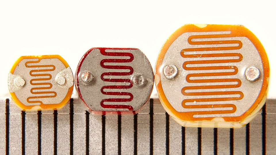
Three cadmium-sulphide photoresistors (LDRs) shown against a millimetre scale. In potential-divider circuits, an LDR’s resistance decreases as light level increases, altering V_out. The image includes scale markings; no extra circuit details are shown. Source.
LDR in a Potential Divider
An LDR can be placed either in the upper or lower arm of a potential divider, depending on whether a direct or inverse response to light intensity is desired.
If the LDR is on the lower arm (connected to ground):
In bright light, resistance falls → voltage drop across LDR decreases → output voltage decreases.
If the LDR is on the upper arm:
In bright light, resistance falls → smaller voltage drop across the fixed resistor → output voltage increases.
This versatility allows engineers to design circuits that respond predictably to changing light levels.
EQUATION
—-----------------------------------------------------------------
Potential Divider Output (V_out) = (R₂ / (R₁ + R₂)) × V_in
V_out = Output voltage (V)
R₁, R₂ = Resistances of the two arms (Ω)
V_in = Input voltage (V)
—-----------------------------------------------------------------
“In a two-resistor divider, the output across R₂ is V_out = (R₂/(R₁+R₂)) V_in.”
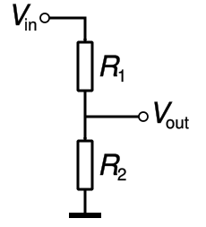
Schematic of a basic two-resistor potential divider with V_in, R₁, R₂, and V_out annotated. Replacing R₁ or R₂ with an LDR or thermistor turns this into a light- or temperature-sensing circuit. The same formula predicts how V_out changes as the sensor’s resistance varies. Source.
By substituting the LDR’s variable resistance for either R₁ or R₂, the output voltage changes with illumination. This behaviour forms the basis for automatic night lights, where increased darkness raises the voltage at a transistor base to activate a lamp.
Thermistors
Structure and Behaviour
A thermistor is a temperature-dependent resistor whose resistance changes with temperature. Most thermistors used in A-Level Physics are Negative Temperature Coefficient (NTC) types.
Thermistor: A resistor whose resistance decreases as temperature increases, typically made of a semiconducting material exhibiting negative temperature coefficient behaviour.
In an NTC thermistor, heating causes more electrons to enter the conduction band, reducing resistance sharply. Conversely, in cooling, fewer charge carriers are available, leading to higher resistance.
“A negative-temperature-coefficient (NTC) thermistor has a resistance that decreases as temperature increases, so the V_out response depends on its position in the divider.”
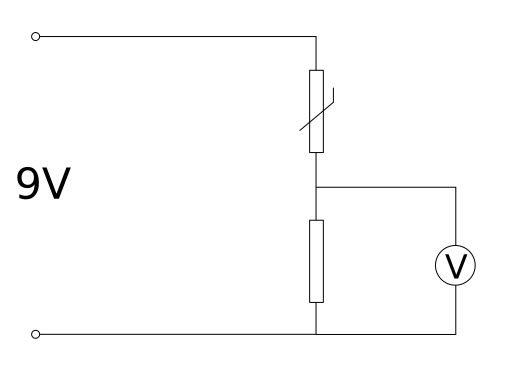
Potential divider using an NTC thermistor and a fixed resistor. As temperature rises, the thermistor’s resistance falls, changing the voltage across the output terminals. The orientation of the thermistor (upper vs lower arm) determines whether V_out increases or decreases with temperature. Source.
Thermistor in a Potential Divider
Like an LDR, a thermistor can be used in either position of a potential divider depending on the desired response.
If the thermistor is in the lower arm:
When temperature rises, resistance decreases → voltage across thermistor decreases → output voltage decreases.
If the thermistor is in the upper arm:
When temperature rises, resistance decreases → more voltage across fixed resistor → output voltage increases.
This configuration enables practical temperature sensors such as automatic fans or thermostats. The output voltage serves as a signal that can trigger further components, such as transistors, relays, or microcontrollers.
Sensor Circuit Design Considerations
1. Sensitivity and Range
The sensitivity of the circuit—the rate of voltage change for a given physical change—depends on the values and arrangement of resistors.
A large fixed resistor paired with an LDR or thermistor enhances sensitivity in the region where resistance changes most rapidly.
Selecting the right resistor combination allows for maximum voltage swing across expected environmental conditions.
2. Choice of Fixed Resistor
To achieve optimal performance:
Choose a fixed resistor with a resistance roughly equal to the variable component’s resistance at mid-range conditions (e.g., average room light or temperature).
This ensures that small changes in light or temperature produce significant changes in output voltage.
3. Power Supply and Component Ratings
The supply voltage (V_in) must match the ratings of the components to prevent overheating or saturation. Using a stable DC supply ensures consistent sensor performance.
4. Use of Output Voltage
The output voltage (V_out) can be:
Measured directly with a voltmeter for calibration or experimentation.
Used to control switching circuits or analogue-to-digital converters in automated systems.
Applications of LDR and Thermistor Circuits
LDR-Based Systems
Automatic lighting systems: Streetlights that switch on when ambient light drops below a threshold.
Camera exposure meters: Adjust shutter speed or aperture depending on scene brightness.
Display brightness controls: Screen illumination adapts to surrounding light levels.
Thermistor-Based Systems
Thermostatic control: Switching heaters or fans based on ambient temperature.
Safety circuits: Monitoring motor or battery temperatures to prevent overheating.
Environmental sensors: Measuring temperature variations in scientific or industrial monitoring.
Each application relies on predictable resistance changes within the potential divider, converting physical inputs into electrical responses that can be processed by control systems.
Design Optimisation and Experimental Use
When designing and testing such circuits, ensure that:
All components are securely connected to avoid fluctuating resistance values.
The voltmeter’s internal resistance is high enough to prevent loading effects.
Temperature or light levels are altered gradually to observe steady-state responses.
Recording V_out at various conditions allows students to construct response curves, showing the relationship between voltage and the measured variable (light or temperature). These plots demonstrate how potential dividers form the foundation of sensing and control systems across modern technologies.
Practice Questions
Question 1 (2 marks)
A student builds a potential divider circuit using an LDR and a fixed resistor connected to a 6.0 V supply. The output voltage is taken across the LDR.
Explain how the output voltage changes when the light intensity on the LDR increases.
Mark scheme:
1 mark: States that the resistance of the LDR decreases as light intensity increases.
1 mark: States that the output voltage (across the LDR) decreases because a smaller proportion of the supply voltage is dropped across the LDR.
Question 2 (5 marks)
A potential divider circuit is set up using a thermistor and a 10 kΩ fixed resistor connected to a 5.0 V supply. The output voltage is measured across the fixed resistor.
(a) Explain how the output voltage changes as the temperature of the thermistor increases. (2 marks)
(b) Suggest one application of this type of circuit and explain how the circuit performs its function. (3 marks)
Mark scheme:
(a)
1 mark: States that as temperature increases, the resistance of the thermistor decreases.
1 mark: Explains that this causes a larger potential difference across the fixed resistor, so the output voltage increases.
(b)
1 mark: Gives a valid application such as a temperature-controlled fan, thermostat, or overheat warning system.
1 mark: States that at higher temperatures, the thermistor’s resistance decreases, increasing the output voltage.
1 mark: Explains that the increased output voltage can be used to trigger another component (e.g., transistor, relay, or control circuit) to switch on a device such as a fan or alarm.
FAQ
Accuracy can be influenced by several factors:
Temperature drift: The resistance of an LDR can vary slightly with temperature, introducing minor errors in light-based measurements.
Component tolerance: Manufacturing variations in resistors or sensors can cause small differences in resistance values.
Contact resistance: Loose or oxidised connections increase unwanted resistance and alter output voltage readings.
Ambient conditions: Dust, humidity, or ageing of the sensing surface can change how much light or heat reaches the sensor.
Careful calibration and consistent environmental conditions improve measurement accuracy.
A high-resistance voltmeter minimises the loading effect on the circuit. If the voltmeter’s resistance is too low, it effectively forms a parallel path with the component across which it is connected, changing the total resistance of that section.
This alters the current distribution and the measured voltage, giving an inaccurate V_out.
Digital voltmeters typically have internal resistances above 10 MΩ, which keeps the loading effect negligible and ensures accurate potential difference readings.
To detect quick variations, such as flickering or moving shadows, an LDR can be combined with a capacitor and resistor network to form a differentiating circuit.
The capacitor charges and discharges as light intensity changes, creating a voltage pulse only during transitions.
Constant light levels result in no change in output voltage, while sudden light changes generate brief voltage spikes.
This method allows circuits to trigger responses only during dynamic lighting conditions, useful for motion or flash detection systems.
NTC (Negative Temperature Coefficient) thermistors are preferred because their resistance decreases smoothly and predictably with increasing temperature, producing a clear, monotonic voltage response in a potential divider.
In contrast, PTC (Positive Temperature Coefficient) thermistors exhibit a sharp increase in resistance beyond a certain temperature threshold, which is useful for protection circuits but not ideal for continuous sensing.
NTC devices provide better linearity and sensitivity within typical environmental temperature ranges, making them ideal for control and measurement applications.
Sensitivity can be enhanced by adjusting component values and circuit design:
Use a fixed resistor with a resistance similar to the sensor’s mid-range resistance.
Operate within the sensor’s most responsive range, where resistance changes steeply with light or temperature.
Employ an amplifier circuit (e.g., using an operational amplifier) to increase the voltage change detected at V_out.
Keep the supply voltage stable, as fluctuations can reduce measurement precision.
Fine-tuning these factors improves the circuit’s ability to detect small environmental changes accurately.
