
OCR Specification focus:
‘Design temperature and light-sensing circuits using potential dividers effectively.’
Practical sensing systems use potential dividers to convert environmental changes, such as light or temperature variations, into measurable voltage signals for control, monitoring, and automation applications across electronics.
Designing Practical Sensing Systems
Designing practical sensing systems involves applying the potential divider principle to produce an output voltage that depends on a changing physical condition, such as light intensity or temperature. By combining variable resistive components—commonly light-dependent resistors (LDRs) and thermistors—with fixed resistors, a potential divider can provide a predictable, adjustable output voltage for controlling devices or feeding into measurement instruments like voltmeters or data loggers.
The Potential Divider Principle
A potential divider is a simple resistive circuit that splits an input voltage into portions proportional to the resistance of its components.

Schematic of a two-resistor potential divider showing V_in, resistors R₁ and R₂, and the tap for V_out. The divider produces an output proportional to the resistance ratio, forming the basis of sensor circuits. The image contains only the essential elements required by the syllabus. Source.
EQUATION
—-----------------------------------------------------------------
Potential Divider Equation (V_out) = (R₂ / (R₁ + R₂)) × V_in
V_out = Output voltage (V)
R₁, R₂ = Resistor values (Ω)
V_in = Input voltage (V)
—-----------------------------------------------------------------
This equation forms the mathematical foundation for designing sensing systems, as it relates output voltage to the ratio of resistances. In sensor applications, one of the resistors changes its resistance according to an environmental factor, causing V_out to vary correspondingly.
Designing Temperature-Sensing Circuits
Temperature-sensing systems typically employ a negative temperature coefficient (NTC) thermistor, whose resistance decreases as temperature increases.
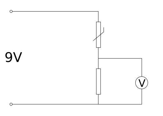
Potential-divider temperature sensor with an NTC thermistor and a fixed resistor producing a voltage that varies with temperature. Placing the thermistor as the upper or lower element sets whether V_out rises or falls with temperature. The diagram focuses on the divider; any external comparator or controller is not shown, in line with the syllabus scope. Source.
The thermistor can be positioned either as the upper or lower resistor in the divider, depending on the desired voltage-temperature relationship.
Configurations
Thermistor in lower position (R₂):
As temperature increases, resistance decreases.
V_out decreases with temperature rise.
Suitable for circuits where high temperature must result in a low output signal.
Thermistor in upper position (R₁):
As temperature increases, resistance decreases.
V_out increases with temperature rise.
Ideal for systems where high temperature triggers a higher control voltage.
In each design, it is important to select a fixed resistor of comparable resistance to the thermistor at the midpoint of the operating temperature range. This maximises sensitivity and ensures a linear response within the desired range.
Designing Light-Sensing Circuits
Light-sensing circuits use an LDR (light-dependent resistor), whose resistance decreases with increasing light intensity. This property allows the circuit to convert variations in illumination into corresponding voltage changes.
Configurations
LDR in lower position (R₂):
Bright light → lower resistance → lower V_out.
Suitable for automatic lighting control where darkness increases V_out to activate lamps.
LDR in upper position (R₁):
Bright light → lower resistance → higher V_out.
Useful in circuits where high light intensity increases control voltage (e.g., for display dimming systems).
These configurations form the basis for automatic systems such as streetlights, camera exposure controls, and light-activated alarms.
Sensor Characteristics and Circuit Matching
The design process requires understanding the characteristic curves of LDRs and thermistors, which show how resistance varies with the physical variable. These curves are typically non-linear, meaning sensitivity varies with temperature or light level. For optimal operation, the resistor ratio should be chosen so that the output voltage changes significantly within the range of interest.
Key design considerations include:
Supply voltage (V_in):
Must be constant for reliable readings.Sensor resistance range:
Select fixed resistors to match mid-range sensor values.Linearisation:
For better accuracy, small operational ranges can approximate linear behaviour.Calibration:
Measured voltage values should be compared against known environmental conditions to ensure reliability
Interfacing with Control and Measurement Devices
Practical sensing systems often interface with microcontrollers, comparators, or operational amplifiers. The output voltage (V_out) can serve as an input to a comparator circuit, triggering a device when the voltage exceeds a threshold. For instance:
A temperature alarm may activate when V_out falls below a set level.
A light-activated relay may switch on when V_out rises above a threshold.
For data acquisition, the output may be fed into an analogue-to-digital converter (ADC), enabling digital systems to interpret sensor responses. Proper impedance matching ensures minimal loading effect, maintaining accurate voltage readings.
Practical Design Steps
When designing a sensing circuit, students should follow a structured approach:
Identify the physical variable to measure (temperature or light).
Choose a suitable sensor component (NTC thermistor or LDR).
Determine the supply voltage appropriate for the circuit.
Select a fixed resistor that balances sensitivity and stability.
Connect the components in the required potential divider configuration.
Measure the output voltage at different conditions.
Adjust resistor values for the desired voltage-response profile.
Include protective components (fuses or current-limiting resistors) where appropriate.
Circuit Design Considerations and Limitations
While potential divider circuits are simple and effective, practical designs must consider limitations and real-world influences:
Loading effects:
When a voltmeter or external circuit is connected, it effectively adds parallel resistance, reducing measured voltage.Temperature drift:
Ambient temperature variations can affect both sensor and resistor characteristics.Power dissipation:
Excessive current through resistors may alter readings or damage components.Response time:
Some sensors, particularly thermistors, respond slowly to environmental changes.Noise and interference:
Electrical noise may cause output fluctuations; shielding and filtering may be necessary.
By anticipating these effects, designers can ensure their sensing systems remain accurate, responsive, and safe under various operating conditions.
Application Examples in Practical Systems
Potential divider-based sensing systems are integral to modern automation and measurement technologies. Examples include:
Automatic lighting controls responding to daylight levels.
Climate-control systems adjusting heating based on ambient temperature.
Safety alarms that trigger under high-temperature or darkness conditions.
Industrial monitoring circuits providing analogue feedback to control systems.
Each application relies on the same fundamental principle: converting physical variations into corresponding electrical signals through effective use of the potential divider.
Practice Questions
Question 1 (2 marks)
A student designs a light-sensing circuit using a potential divider that contains an LDR and a fixed resistor. The output voltage (V_out) is taken across the LDR.
Explain how the output voltage changes when the light intensity on the LDR increases.
Mark scheme
1 mark: States that as light intensity increases, the resistance of the LDR decreases.
1 mark: States that as the LDR resistance decreases, the output voltage (V_out) across it also decreases.
Question 2 (5 marks)
A student builds a temperature-sensing system using a potential divider with a 12 V power supply, a fixed resistor of 2.0 kΩ, and an NTC thermistor.
(a) Explain how this circuit can be used to detect when the temperature of a room exceeds a set value.
(b) Describe how this system could be adapted to operate an alarm when the temperature becomes too high.
Mark scheme
(a)
1 mark: Mentions that as temperature increases, the thermistor’s resistance decreases (NTC behaviour).
1 mark: Explains that the potential divider causes the output voltage (V_out) across the thermistor to decrease with increasing temperature.
1 mark: States that the change in V_out can be compared with a fixed reference voltage to detect when the temperature passes a threshold.
(b)
1 mark: Explains that a comparator (or operational amplifier used as a comparator) can compare V_out with a reference voltage.
1 mark: States that when V_out falls below the reference voltage, the comparator output can trigger an alarm or relay circuit to sound.
FAQ
Sensitivity depends on how much the output voltage changes for a given change in the physical quantity being measured. It is influenced by:
The ratio of the fixed resistor to the variable resistor (LDR or thermistor).
The operating range of the sensor, since non-linear characteristics can make certain regions more or less sensitive.
The supply voltage, as higher voltages produce larger potential differences and clearer voltage changes.
Choosing resistor values that keep the variable component near its mid-range resistance typically gives the most sensitive response.
The direction of response can be reversed by swapping the positions of the fixed resistor and the variable component.
If the LDR or thermistor is placed in the lower part of the divider, output voltage decreases when resistance falls.
Placing it in the upper position causes output voltage to increase when resistance falls.
This allows flexibility in designing circuits for different trigger conditions or control requirements.
Many sensors, such as thermistors, have non-linear resistance characteristics, meaning the output voltage does not change uniformly with temperature or light intensity.
Linearisation simplifies calibration and improves the accuracy of readings across a defined range.
Techniques include:
Restricting operation to a small range where the sensor’s response is nearly linear.
Adding parallel or series resistors to modify the overall curve.
Using electronic compensation through amplifiers or microcontroller software.
Potential divider sensors offer:
Simplicity: Only two resistive components and a voltage source are required.
Adjustability: Output voltage can be tuned by selecting resistor values or using variable resistors.
Compatibility: The output is a voltage signal, easily interfaced with comparators, ADCs, and microcontrollers.
Low cost: Components are inexpensive and consume little power.
These properties make them ideal for educational projects and real-world applications like thermostats and light-control systems.
Calibration ensures that output voltage corresponds accurately to the measured quantity.
Process:
Expose the sensor to known reference conditions (e.g., controlled temperatures or measured light levels).
Record the output voltage at each condition.
Plot voltage against the physical variable to establish a calibration curve.
Use this curve or a fitted equation to convert voltage readings during normal operation.
Regular calibration accounts for component drift and environmental effects, improving long-term accuracy.
