
OCR Specification focus:
‘A potential divider splits input p.d.; a potentiometer is a variable potential divider.’
A potential divider is a fundamental concept in circuit design, allowing a single voltage supply to produce a range of lower output voltages. It underpins the operation of many sensing and control systems, including potentiometers, LDR and thermistor circuits. Understanding how potential dividers work is essential for analysing and designing voltage-based electronic systems.
The Potential Divider Concept
A potential divider is a circuit that uses two or more resistors connected in series across a voltage source to produce a fraction of the total potential difference (p.d.) across part of the circuit. It enables a designer to control or select a desired output voltage from a constant input.
Potential Divider: A circuit arrangement that divides an input potential difference into smaller, controlled voltages using a series of resistors.
The principle of the potential divider relies on Ohm’s law and the fact that the total voltage across resistors in series is distributed in proportion to their resistances. This relationship means that by varying the resistance ratio, the output voltage can be adjusted to any desired value within the supply range.
Basic Structure and Function
A basic potential divider consists of:
A voltage source (V_in) connected across two resistors R₁ and R₂ in series.
An output voltage (V_out) taken across one of the resistors, usually R₂.
The current through both resistors is the same because they are in series. The voltage across each resistor is proportional to its resistance. Therefore, the resistor ratio determines how much of the total supply voltage appears at the output.
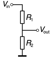
A labelled circuit diagram of a two-resistor potential divider showing Vin, Vout, R₁, and R₂. The output p.d. is taken across R₂, visualising the divider action defined by the resistance ratio. The diagram contains only the elements required by the syllabus. Source.
EQUATION
—-----------------------------------------------------------------
Potential Divider Equation (V_out) = (R₂ / (R₁ + R₂)) × V_in
V_out = Output voltage (V)
R₁, R₂ = Resistances (Ω)
V_in = Input voltage (V)
—-----------------------------------------------------------------
This relationship provides a simple and predictable means of producing a controlled voltage from a fixed supply, which is a core requirement in measurement and control circuits.
Understanding Voltage Ratios and Control
The proportional nature of voltage division means that small changes in resistance can lead to significant variations in output voltage. This feature is exploited in sensors and adjustable controls such as volume knobs and dimmer switches. For example, if R₂ is increased relative to R₁, a greater proportion of the supply voltage appears across R₂, increasing the output voltage.
In more complex circuits, multiple resistors or combinations of resistors and sensors can form potential divider networks to produce multiple voltage levels or automatically vary voltage with changing physical conditions.
The Potentiometer as a Variable Potential Divider
A potentiometer is a specific type of variable resistor used as a continuously adjustable potential divider. It typically consists of a resistive track with a movable contact (the wiper) that can slide along the track, effectively changing the resistance ratio between two parts of the circuit.
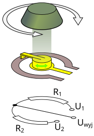
A clear potentiometer diagram showing terminals at each end of the resistive track and a movable wiper contact. Moving the wiper changes the resistance ratio, so V_out varies smoothly from 0 to V_in. Extra detail: the original diagram is general-purpose and does not include numerical values, which are not required by the syllabus. Source.
Potentiometer: A variable resistor that acts as a continuously adjustable potential divider, producing an output voltage that depends on the wiper position.
When the potentiometer is connected across a fixed voltage supply:
The total resistance of the track is constant.
Moving the wiper alters the proportion of the resistance on either side, thereby changing the voltage across the output terminals.
The output voltage taken between one end of the track and the wiper can vary smoothly from 0 V up to the full supply voltage.
This smooth variability makes potentiometers ideal for manual controls in audio, lighting, and instrumentation systems.
Electrical Behaviour of a Potentiometer
A potentiometer essentially implements the potential divider equation in a continuously variable form. If the total resistance is R_total and the wiper divides it into resistances R₁ and R₂, then:
EQUATION
—-----------------------------------------------------------------
Potentiometer Output Voltage (V_out) = (R₂ / (R₁ + R₂)) × V_in
R₁ = Resistance from one terminal to the wiper (Ω)
R₂ = Resistance from the wiper to the other terminal (Ω)
V_in = Input supply voltage (V)
—-----------------------------------------------------------------
The output can be adjusted from 0 V (when the wiper is at the ground end) to V_in (when the wiper is at the supply end). The linearity and smoothness of this variation depend on the uniformity of the resistive track.
Practical Applications of Potential Dividers and Potentiometers
Potential dividers are central to many electronic measurement and control systems. Common uses include:
Sensor circuits: to convert physical changes (e.g. light or temperature) into voltage signals.
Analogue input control: in devices such as volume controls, dimmers, and tuning knobs.
Reference voltage generation: to provide a stable but reduced voltage for specific components.
Voltage level adjustment: to interface components operating at different voltage ranges.
In laboratory and educational contexts, potential dividers also serve as clear examples of the relationship between voltage, current, and resistance, reinforcing the principles of Ohm’s law and energy conservation.
Design Considerations
When designing a potential divider circuit:
The load resistance connected across the output must be large compared to the divider resistors to prevent current draw from altering the output voltage.
The power rating of resistors must be sufficient to handle energy dissipation safely.
Tolerances in resistor values can affect the accuracy of the divided voltage.
Temperature coefficients of resistors may alter resistance and therefore voltage stability.
For potentiometers:
The choice between linear and logarithmic tracks depends on the intended use (e.g. logarithmic for audio volume control).
Mechanical wear and dust can affect reliability, particularly in analogue systems.
Precision potentiometers or digital equivalents are used in applications requiring stable and repeatable settings.
Summary of Key Principles
A potential divider splits an input voltage into smaller parts based on resistor ratios.
A potentiometer acts as a variable potential divider, offering a continuously adjustable output.
The output voltage depends directly on the ratio of resistances, not their absolute values.
These principles underpin many control and sensing applications in physics and engineering.
Practice Questions
Question 1 (2 marks)
A student sets up a potential divider circuit using two resistors, R1 and R2, connected in series across a 6.0 V power supply.
Explain how the ratio of R1 to R2 affects the output voltage across R2.
Mark scheme:
1 mark: States that the voltage across each resistor depends on its proportion of the total resistance.
1 mark: Explains that increasing R2 (relative to R1) increases the output voltage across R2 because it takes a larger share of the total potential difference.
Question 2 (5 marks)
A potentiometer is connected across a 9.0 V supply and used to vary the voltage supplied to a small motor. The total resistance of the potentiometer is 12 kΩ.
(a) Explain how the potentiometer controls the voltage supplied to the motor. (2 marks)
(b) State and explain what happens to the motor voltage as the wiper moves from one end of the potentiometer to the other. (3 marks)
Mark scheme:
(a)
1 mark: The potentiometer divides the input voltage according to the resistance ratio on either side of the wiper.
1 mark: Moving the wiper changes these resistances, altering the output (motor) voltage.
(b)
1 mark: When the wiper is at one end, the motor receives 0 V (connected to the zero potential end).
1 mark: When the wiper is at the other end, the motor receives the full 9.0 V (connected to the supply end).
1 mark: The voltage increases smoothly between these two limits as the wiper moves, because the division of resistance is continuous along the track.
FAQ
Inaccuracies can arise from several practical factors:
Resistor tolerance: Real resistors have manufacturing tolerances, meaning their resistance values may vary by ±1% to ±10%.
Temperature variation: Resistance changes with temperature, altering the voltage ratio.
Contact resistance: Poor or corroded connections increase unwanted resistance.
Loading effect: If a device connected across the output draws significant current, it alters the voltage distribution.
To reduce inaccuracies, use precision resistors, stable temperature conditions, and ensure the load resistance is much larger than the divider resistances.
The internal resistance of a power supply reduces the total voltage available to the circuit. In a potential divider, this means the input voltage (V_in) is slightly less than the ideal supply voltage.
This reduction causes a smaller-than-expected output voltage. The effect becomes more pronounced if the total resistance of the divider is low, since a larger current flows and more voltage is lost across the internal resistance.
To minimise this, use higher-value resistors in the divider or a supply with low internal resistance.
Potentiometers provide continuous adjustability, allowing precise manual control of the output voltage.
They are especially useful in:
Volume or brightness controls where gradual variation is needed.
Calibration circuits requiring fine voltage tuning.
Fixed resistor dividers, while more stable, only provide a single voltage ratio. Potentiometers introduce flexibility but can wear mechanically or drift slightly due to movement and dust ingress.
A linear potentiometer changes resistance evenly as the wiper moves — equal mechanical movement produces equal voltage change.
A logarithmic potentiometer changes resistance non-linearly, following a logarithmic curve. This means the voltage changes gradually at one end of the rotation and rapidly at the other.
Logarithmic potentiometers are used where human perception is non-linear, such as sound intensity (volume) or light brightness controls. Linear types are better for measurement and proportional control circuits.
Potential dividers can include variable resistors that respond to environmental changes, such as:
LDRs (light-dependent resistors) for light sensing
Thermistors for temperature sensing
When used in place of one resistor in the divider, the output voltage varies automatically with changing light or temperature.
This principle underpins many automatic systems, such as night lights, thermostats, and climate sensors, where the varying voltage acts as an input signal for further control or switching circuitry.
