
OCR Specification focus:
‘Explain plane polarisation; demonstrate with polarising filters and microwave grilles.’
Polarisation reveals how electromagnetic (EM) waves oscillate and interact with matter. It demonstrates the transverse nature of EM waves and underpins technologies such as photography, communications, and liquid-crystal displays (LCDs).
Nature of Polarisation
Polarisation is a distinctive property of transverse waves, in which the oscillations occur perpendicular to the direction of wave travel. It does not occur in longitudinal waves, where oscillations are parallel to propagation direction.
Polarisation: The process by which the vibrations of a transverse wave are restricted to one plane.
In unpolarised light, such as sunlight or light from a filament bulb, the electric field vectors vibrate in all possible planes perpendicular to the direction of travel. Polarisation limits these vibrations to a single plane, producing plane-polarised light.
Electromagnetic Wave Structure
An electromagnetic wave consists of mutually perpendicular oscillating electric (E) and magnetic (B) fields, both perpendicular to the direction of propagation. The electric field direction defines the plane of polarisation.
Light, microwaves, and radio waves are all transverse, so they can be polarised. Sound, being longitudinal, cannot be polarised.
Methods of Producing Plane Polarisation
1. Polarising Filters
Polaroid filters are materials containing aligned long-chain molecules that absorb electric field vibrations in one direction while transmitting those perpendicular to it.
When unpolarised light passes through a polarising filter:
Only vibrations parallel to the transmission axis emerge.
The transmitted light is plane-polarised.
The intensity of the transmitted light depends on the angle between the light’s electric field and the filter’s transmission axis.
2. Double Polarisation (Using Two Filters)
When two polarising filters are used:
The first (the polariser) produces plane-polarised light.
The second (the analyser) is rotated to examine polarisation effects.
If the analyser’s transmission axis is parallel to the polariser, maximum intensity is transmitted.
If it is perpendicular, no light is transmitted — the screen appears dark.
EQUATION
—-----------------------------------------------------------------
Malus’s Law (I) = I₀ cos²θ
I = Transmitted light intensity (W m⁻²)
I₀ = Initial light intensity (W m⁻²)
θ = Angle between polariser and analyser transmission axes (degrees or radians)
—-----------------------------------------------------------------
Malus’s law quantifies how transmitted light intensity varies with the relative angle of two polarising filters. It provides strong evidence that light behaves as a transverse wave.
3. Polarisation by Reflection
When light reflects off certain surfaces, such as water, glass, or roads, it becomes partially plane-polarised.
At a particular angle, called the Brewster angle, the reflected and refracted rays are at right angles.
The reflected light is then completely polarised in a direction parallel to the reflecting surface.
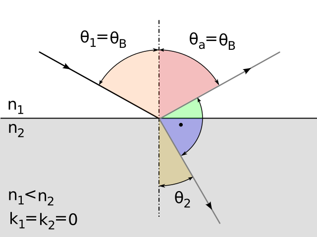
Labelled sketch of light at the Brewster angle with incident, reflected, and refracted rays and the surface normal. At this angle, the reflected beam is fully p-polarised, matching the statement that glare from water or glass is strongly polarised parallel to the surface. The diagram cleanly indicates the angle and ray geometry without extraneous details. Source.
Brewster Angle (θ₍B₎): The angle of incidence at which light reflected from a surface is completely plane-polarised.
EQUATION
—-----------------------------------------------------------------
Brewster’s Law (θ₍B₎) = tan⁻¹(n₂/n₁)
n₁ = Refractive index of the first medium
n₂ = Refractive index of the second medium
—-----------------------------------------------------------------
This phenomenon is why polarised sunglasses reduce glare: they contain filters that block horizontally polarised light reflected from flat surfaces.
4. Polarisation by Scattering
When sunlight passes through the atmosphere, scattering by air molecules causes partial polarisation of the sky’s light.
The effect is strongest at 90° to the Sun’s direction.
This polarisation explains why polarising filters used in photography can darken blue skies and enhance contrast.
Demonstrating Polarisation
Using Polarising Filters (Light Waves)
Practical demonstration steps:
Pass unpolarised light (from a lamp) through one polarising filter.
Rotate a second filter (the analyser) and observe light intensity variations.
Darkness at 90° rotation confirms plane polarisation.
The pattern repeats every 180°, consistent with Malus’s law.
Using Microwave Grilles (Microwave Polarisation)
Microwave polarisation experiments mirror those with visible light but operate in the radio frequency range.
Microwaves are produced by a transmitter and detected by a receiver with a metal grille.
The grille consists of parallel metal rods that absorb the electric field component parallel to them.
When the rods are parallel to the electric field, absorption is maximum, and the receiver detects minimal signal.
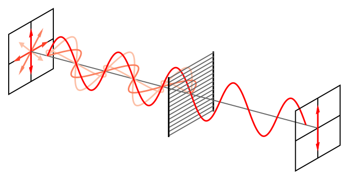
Diagram of a wire-grid polariser: EM waves with E parallel to the wires drive currents and are absorbed, while the component perpendicular to the wires passes. This models the classroom microwave experiment with a transmitter, rotatable grid, and receiver, directly evidencing that microwaves are transverse and polarisable. Source.
When rods are perpendicular, the electric field passes freely, giving maximum signal.
This demonstrates that microwaves are polarised transverse waves and share the same fundamental properties as light.
Analysing Polarisation in Different Contexts
Polarisation in Communication Systems
Modern communication systems exploit polarisation to improve signal clarity and data capacity.
Satellite transmissions often use orthogonal polarisations (horizontal and vertical) to double channel capacity without interference.
Antenna alignment is crucial: the transmitting and receiving antennas must share the same polarisation orientation for maximum signal strength.
Polarisation in Optical Devices
Liquid crystal displays (LCDs) depend on polarisation control.
LCD panels contain two crossed polarising filters.
Between them lies a liquid crystal layer that rotates the polarisation of light under an applied voltage.
This selective transmission of light through the second polariser forms the visible display image.
Biological and Everyday Applications
Insects such as bees use polarised skylight for navigation.
Photographers use polarising filters to reduce reflections and enhance contrast.
3D cinema glasses employ orthogonal polarisations to separate images for the left and right eyes, creating the stereoscopic effect.
Key Insights
Polarisation provides conclusive evidence that electromagnetic waves are transverse. It underpins technologies from optics to communications and serves as a core concept in wave physics. Through filters, reflection, and scattering, the orientation of electric field vibrations becomes observable, connecting theory to practical understanding in both visible and non-visible EM wave phenomena.
Practice Questions
Question 1 (2 marks)
Explain what is meant by plane polarisation and state why only transverse waves can be polarised.
Mark Scheme:
1 mark: Correctly states that plane polarisation is when the oscillations of a transverse wave are confined to one plane perpendicular to the direction of propagation.
1 mark: States that only transverse waves can be polarised because their oscillations occur perpendicular to the direction of energy transfer, allowing restriction to a single plane (longitudinal waves oscillate parallel and cannot be restricted this way).
Question 2 (5 marks)
A student investigates the polarisation of light using two polarising filters.
(a) Describe and explain what the student would observe as one filter is slowly rotated from 0° to 90° relative to the other. (3 marks)
(b) State and explain how this experiment demonstrates that light is a transverse wave. (2 marks)
Mark Scheme:
(a)
1 mark: At 0°, maximum light intensity is transmitted (filters’ transmission axes aligned).
1 mark: As the analyser rotates, light intensity decreases gradually.
1 mark: At 90°, almost no light is transmitted (axes perpendicular), showing light intensity varies with the cosine squared of the angle between the axes (Malus’s law).
(b)
1 mark: Only transverse waves can have their oscillations restricted to a single plane, as seen here.
1 mark: Therefore, the variation in transmitted intensity with filter rotation provides evidence that light is a transverse wave.
FAQ
Birefringent materials have two refractive indices because their structure causes light polarised in different planes to travel at different speeds. When plane-polarised light enters such a material, it splits into two rays: the ordinary ray and the extraordinary ray, each vibrating in perpendicular planes.
This separation produces a phase difference between the rays. When recombined, they can form new polarisation states — elliptical or circular — depending on the thickness and orientation of the material.
At most angles of incidence, both perpendicular and parallel components of the electric field are reflected, but with different intensities.
This imbalance means the reflected wave is not completely polarised, but the component parallel to the surface is dominant. As the angle approaches the Brewster angle, the reflected and refracted rays become closer to 90°, increasing the degree of polarisation until total plane polarisation occurs exactly at Brewster’s angle.
Yes, circular and elliptical polarisation occur when two perpendicular electric field components have a phase difference (usually 90°) and possibly different amplitudes.
Circular polarisation: equal amplitudes and a 90° phase shift; the electric field vector rotates uniformly.
Elliptical polarisation: unequal amplitudes or a phase difference not equal to 90°.
Unlike plane polarisation, where the electric field oscillates in a fixed plane, these types involve the electric field rotating as the wave propagates.
Polaroid filters are made of long, chain-like molecules aligned in one direction. These molecules act like tiny antennas that absorb electric field vibrations parallel to their alignment by inducing electron motion along their length.
Vibrations perpendicular to the molecular alignment pass through unaffected.
This selective absorption converts unpolarised light into plane-polarised light, with oscillations restricted to one plane perpendicular to the absorbing direction.
LCD screens use two crossed polarising filters with a liquid crystal layer between them that twists the plane of polarisation of light.
When a viewer adds another external polarising filter:
If its transmission axis aligns with the screen’s polarisation, light passes, and the image remains visible.
If it is rotated 90°, the external filter blocks the rotated light, causing the screen to appear dark.
This interaction demonstrates control of polarised light in display technologies.
