OCR Specification focus:
‘Use diffraction patterns to infer particle wavelength and material structure.’
Interpreting diffraction patterns allows physicists to understand the wave-like behaviour of particles and to deduce information about both the wavelength of electrons and the structure of materials they interact with. This process forms crucial evidence for wave–particle duality, demonstrating that matter exhibits properties of both waves and particles.
Understanding Diffraction Patterns
When electrons or other particles pass through a thin material, such as polycrystalline graphite or a crystal lattice, they interact with the regular atomic spacing of the atoms in the structure. This interaction causes the waves associated with the particles to diffract—that is, to spread out and interfere with one another, producing a distinctive pattern of bright and dark regions on a detecting screen.
The appearance of this pattern reveals vital information. The positions of the bright and dark regions depend on the wavelength of the particles, while the geometry of the pattern provides insight into the spacing and arrangement of atoms in the diffracting material.
Wave Nature and the de Broglie Relationship
de Broglie Wavelength: The wavelength associated with a moving particle, given by λ = h/p, where h is Planck’s constant and p is the particle’s momentum.
This relationship links the momentum of a particle to a wave property — its wavelength. When the de Broglie wavelength (λ) is similar in size to the inter-atomic spacing (d) in a crystal, diffraction becomes observable.
EQUATION
—-----------------------------------------------------------------
de Broglie Equation (λ) = h/p
λ = de Broglie wavelength (metres, m)
h = Planck’s constant (6.63 × 10⁻³⁴ joule seconds, J·s)
p = momentum (kilogram metres per second, kg·m·s⁻¹)
—-----------------------------------------------------------------
This equation is essential for interpreting diffraction patterns because it connects measured diffraction data to the underlying particle properties.
Inferring Particle Wavelength from Diffraction Patterns
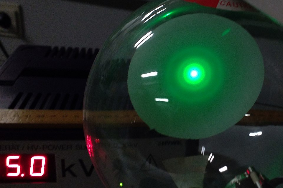
When a beam of electrons strikes a thin crystalline material, the electrons diffract according to the spacing between atomic planes. The pattern typically appears as concentric rings or spots on a fluorescent or phosphorescent screen, depending on whether the material is polycrystalline or a single crystal.

Electron diffraction pattern with distinct concentric rings from a thin polycrystalline sample. The ring radii correspond to different inter-planar spacings, enabling determination of wavelength (via Bragg’s condition) and material structure. This visual directly supports interpreting ring positions to extract structural information. Source.
By analysing these rings, physicists can calculate the wavelength of the electrons:
EQUATION
—-----------------------------------------------------------------
Diffraction Equation (nλ) = 2d sinθ
n = order of diffraction (integer)
λ = wavelength of particle (metres, m)
d = inter-planar spacing in the crystal (metres, m)
θ = diffraction angle (degrees or radians)
—-----------------------------------------------------------------
This Bragg-like relationship shows how constructive interference occurs when the path difference between diffracted waves equals an integer multiple of the wavelength.

Bragg diffraction geometry showing incident and reflected beams from parallel atomic planes with spacing d and angle θ. This construction underpins ring formation: each ring corresponds to a set of planes satisfying 2d sin θ = nλ. Note: the diagram is general for diffraction (often shown for X-rays) but applies identically to electron diffraction interpretation. Source.
Measuring θ from the diffraction pattern allows the determination of λ, which, through the de Broglie relationship, can reveal the momentum or energy of the electrons.
Features of Electron Diffraction Patterns
Key Observations
Concentric rings indicate diffraction through multiple randomly oriented crystals within a polycrystalline target.
Sharp spots occur in single crystals, representing well-defined atomic planes.
The radius of the rings or position of the spots is inversely related to the wavelength of the electrons — shorter wavelengths produce smaller diffraction angles.
As the accelerating voltage (and thus electron speed and momentum) increases, the wavelength decreases, and the diffraction pattern contracts towards the centre.
These observations confirm that electrons behave as waves, providing strong support for wave–particle duality.
Determining Material Structure from Diffraction Patterns
The pattern geometry not only provides information about the electron wavelength, but also about the crystal structure of the material:
The spacing of rings or spots corresponds to the distance between atomic planes in the crystal.
Different intensities within the pattern relate to the arrangement and density of atoms within those planes.
Using known electron energies (and hence known wavelengths), experimentalists can measure the crystal lattice spacing (d) precisely.
This technique forms the basis for methods such as electron diffraction analysis, used to characterise crystalline solids, thin films, and nanostructures.
Relating Diffraction Data to Experimental Parameters
When electrons are accelerated through a known potential difference, their momentum can be determined from their kinetic energy. Substituting this into the de Broglie equation gives their wavelength, which can then be compared to the observed diffraction angles to test theoretical predictions.
EQUATION
—-----------------------------------------------------------------
Electron Wavelength (λ) = h / √(2meV)
λ = electron wavelength (metres, m)
h = Planck’s constant (6.63 × 10⁻³⁴ J·s)
m = electron mass (9.11 × 10⁻³¹ kg)
e = elementary charge (1.60 × 10⁻¹⁹ C)
V = accelerating potential difference (volts, V)
—-----------------------------------------------------------------
By combining the measured ring radii with known experimental geometry, students and scientists can verify the de Broglie hypothesis and determine inter-atomic distances with remarkable accuracy.
Importance in Quantum Physics
Interpreting diffraction patterns bridges the gap between classical and quantum physics. Classical theories cannot explain how particles produce wave interference patterns, yet quantum theory — with its probabilistic wavefunctions — does. The ability to infer both particle wavelength and material structure from these patterns is a striking demonstration that all matter exhibits wave-like properties under suitable conditions.
The experimental interpretation of diffraction patterns therefore provides direct evidence for matter waves, supports the quantum mechanical model of the atom, and reinforces the concept that observable diffraction depends on the relationship between wavelength and atomic spacing.
FAQ
The brightness of each diffraction ring depends on the number of electrons scattered at that specific angle and the atomic arrangement within the crystal planes.
Greater electron density or more closely packed planes produce brighter rings due to stronger constructive interference.
Additionally, the intensity distribution is influenced by the atomic form factor—how individual atoms scatter electrons—and the crystal orientation relative to the beam. In practice, the brightest rings correspond to the most prominent atomic planes within the material.
Polycrystalline materials consist of many tiny crystallites, each oriented randomly. When a parallel electron beam interacts with these grains, diffraction occurs in all possible directions corresponding to different crystal orientations.
As a result, instead of discrete spots (as in a single crystal), the overlapping diffraction cones from many grains form continuous concentric rings on the screen.
Each ring corresponds to a specific set of atomic planes with a distinct spacing, providing measurable information about inter-planar distances.
Increasing the accelerating voltage increases the kinetic energy and therefore the momentum of the electrons. According to the de Broglie equation, this reduces their wavelength.
A shorter wavelength causes smaller diffraction angles, so the rings move closer to the centre of the pattern.
The ring spacing becomes tighter, while their relative positions remain fixed because they depend on atomic spacings, not energy.
This relationship can be used experimentally to verify λ = h / √(2meV) and confirm the predicted behaviour of matter waves.
Electrons accelerated through typical laboratory voltages (a few thousand volts) have wavelengths around 0.05 to 0.2 nanometres, comparable to atomic spacing in solids.
Because of this, electron diffraction can resolve features on the atomic scale, far beyond what visible light can achieve due to its longer wavelength (~500 nanometres).
This makes electron diffraction a powerful tool for studying crystal lattices, thin films, and nanostructures, where fine structural information is required.
Blurring or distortion can result from several practical issues:
Non-uniform film thickness, causing uneven scattering of electrons.
Beam divergence, where the electron beam isn’t perfectly parallel.
Vibrations or magnetic interference, which disturb the beam path.
Thermal motion of atoms, which increases at higher temperatures and weakens the interference pattern.
Careful alignment, stable power supplies, and maintaining vacuum conditions help ensure sharp, measurable diffraction rings.
Practice Questions
Question 1 (2 marks)
An electron beam passes through a thin polycrystalline graphite film and produces a diffraction pattern of concentric rings on a screen.
Explain what this pattern indicates about the nature of electrons.
Mark scheme:
1 mark: States that the rings show that electrons behave as waves or have wave-like properties.
1 mark: Links the observation to electron diffraction or interference, demonstrating wave–particle duality.
Question 2 (5 marks)
Electrons are accelerated through a potential difference and directed at a thin crystal. A diffraction pattern of bright rings appears on a fluorescent screen.
Explain how this diffraction pattern can be used to determine:
(a) the wavelength of the electrons, and
(b) information about the structure of the crystal.
Mark scheme:
1 mark: States that the electron wavelength is related to its momentum using the de Broglie equation (λ = h/p).
1 mark: Recognises that diffraction occurs when the wavelength is comparable to the inter-planar spacing (d) in the crystal.
1 mark: States or implies that constructive interference occurs when 2d sinθ = nλ (Bragg condition).
1 mark: Explains that measuring the diffraction angle (θ) or ring radius allows calculation of λ.
1 mark: Explains that the pattern geometry or ring spacing provides information about atomic spacing or crystal structure (e.g. inter-atomic distances or plane separations).

