
OCR Specification focus:
‘Describe charging and discharging in terms of electron flow to and from capacitor plates.’
Charging and discharging a capacitor involve the microscopic movement of electrons between conductive plates, shaping how electrical energy accumulates and is later released in circuits.
Charging and Discharging at the Electron Level
Microscopic View of a Capacitor
A capacitor is a component consisting of two conductive plates separated by an insulating material. When connected to a power source, the behaviour of the capacitor is governed not by bulk current movement alone, but by electron redistribution on and between its plates. This subsubtopic emphasises understanding these processes at the level of electron flow, a requirement of the OCR specification for this section.
As electrons move, they create charge separation, which results in an increasing potential difference (p.d.) across the capacitor plates.
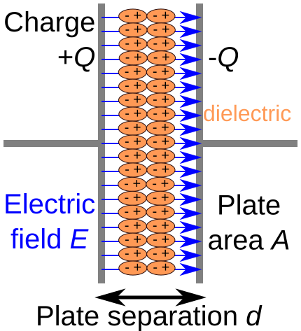
A schematic diagram of a parallel-plate capacitor showing charge on the plates and the resulting electric field across the dielectric. The labelled geometry helps link microscopic charge separation to potential difference. Some geometric details exceed this subsubtopic but remain broadly useful. Source.
The Electron Flow During Charging
When a capacitor is connected to a d.c. power supply, the charging process begins instantly. The essential idea is that electrons are driven away from one plate and accumulate on the other, producing equal and opposite charges. Even though no electrons physically cross the insulating gap, the rearrangement of charge establishes the electric field that gives the capacitor its function.
Key events during charging include:
Connection to a supply: Electrons in the circuit experience a push from the cell’s chemical action.
Electron removal from the positive plate: The supply pulls electrons away, leaving it with a net positive charge.
Electron accumulation on the negative plate: Electrons are deposited onto this plate, giving it a net negative charge.
Growth of electric field: Charge separation builds an internal electric field that increasingly resists further electron movement.
Approach to maximum p.d.: Eventually, the p.d. across the capacitor equals the supply p.d., and current through the circuit falls to zero.
Because the insulator prevents electrons from crossing between the plates, the charging current in the external circuit is the only means of redistributing charge. As more electrons build up, the force opposing further charge transfer increases.
Charge and Plate Behaviour
During charging, the plates effectively act as electron reservoirs, one being depleted and the other enriched. The power supply maintains a flow until the capacitor “fills” in the sense that no further charge redistribution can occur.
Electric field: A region in which a charged particle experiences a force due to the presence of other electric charges.
The growing electric field between the plates shapes the behaviour of electrons in the external circuit, steadily reducing the current as the capacitor approaches its charged state.
A crucial point for students is that current in the capacitor branch falls even though electrons never pass through the insulator. The current reduces because fewer electrons can be forced onto the negatively charged plate as its potential becomes more negative relative to the rest of the circuit.
Electron Flow During Discharge
Discharging reverses the charge movement established during charging.
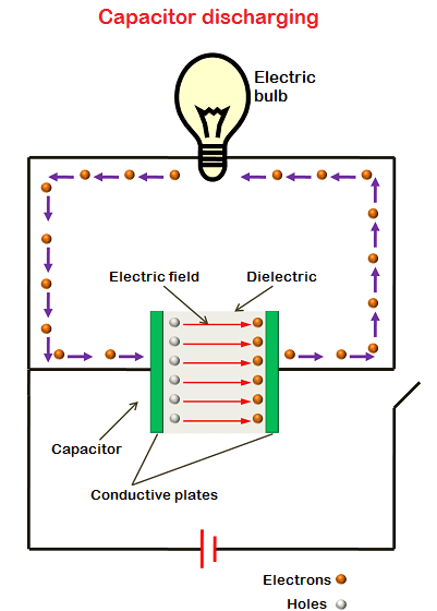
A diagram illustrating a capacitor discharging through a circuit, with electrons flowing from the negatively charged plate toward the positively charged plate. The diminishing electric field between the plates is also indicated. The inclusion of a light bulb shows energy release, which is additional context beyond the strict syllabus requirement. Source.
If the capacitor is connected across a resistor or other conductive path, electrons flow in a direction that reduces the plate imbalance.
During discharging:
Electrons leave the negatively charged plate, flowing through the circuit.
These electrons move towards the positively charged plate, where they neutralise the deficit of electrons.
The electric field inside the capacitor weakens as charge separation diminishes.
The current gradually decreases until the capacitor is fully discharged, at which point there is no longer a potential difference to drive electron movement.
The process is entirely driven by the stored electrical energy in the capacitor, not by any external source. The resistor controls the discharge rate, but the electron flow is released energy being redistributed until equilibrium is reached.
Behaviour of Circuit Quantities
Understanding the electron-level description helps explain the observable behaviour of current and p.d. in the circuit:
At the start of charging, electron flow is rapid, producing a large current.
As the negative plate becomes more negatively charged, additional electrons are repelled, slowing the current.
During discharging, electron flow begins strongly but weakens as the charge difference reduces.
EQUATION
—-----------------------------------------------------------------
Charge–Voltage Relationship (Capacitance): Q = C V
Q = Charge on either plate (coulombs)
C = Capacitance, a measure of charge stored per volt (farads)
V = Potential difference between the plates (volts)
—-----------------------------------------------------------------
This relationship explains why a large charge separation corresponds directly to a larger potential difference: the more electrons that have been transferred, the greater the electric field and the p.d. between the plates.
Summary of Electron-Level Processes
To directly support the OCR requirement to describe charging and discharging at the electron level, the following microscopic points are essential:
Charging involves the removal of electrons from one plate and their accumulation on the opposite plate, driven by the supply.
Discharging involves electron flow back through an external circuit, reducing the charge difference.
No electrons cross the insulating gap; all charge redistribution occurs through external conductive paths.
Plate charge separation establishes the electric field and resulting potential difference across the capacitor.
These concepts form the foundational microscopic picture underpinning capacitor behaviour in later circuit and exponential charging topics.
Practice Questions
Question 1 (2 marks)
Describe what happens to electrons on the plates of a capacitor when it begins to charge after being connected to a d.c. power supply.
Question 1 (2 marks)
• 1 mark: States that electrons are removed from the plate connected to the positive terminal.
• 1 mark: States that electrons flow onto the plate connected to the negative terminal, creating opposite charges on the plates.
Question 2 (5 marks)
A capacitor is fully charged and then connected across a resistor so that it discharges.
Explain, in terms of electron movement and electric field changes, what happens during the discharge process.
In your answer, describe how the current changes, why it changes, and what eventually causes the discharge to stop.
Question 2 (5 marks)
• 1 mark: Electrons leave the negatively charged plate and flow through the external circuit towards the positively charged plate.
• 1 mark: States that this movement reduces the charge separation between the plates.
• 1 mark: Describes that the electric field between the plates weakens as discharge progresses.
• 1 mark: States that the current decreases because the potential difference driving the electron flow becomes smaller as charge separation falls.
• 1 mark: States that discharge stops when there is no potential difference left across the plates, so no force acts to move electrons.
FAQ
Electron drift speed is extremely slow, often only a few millimetres per second, even when current is flowing. This surprises many students who imagine electrons racing through the wires.
The rapid response of a circuit comes from the electric field, which propagates through the conductor at a significant fraction of the speed of light, pushing electrons almost simultaneously throughout the circuit.
The insulator has no free charge carriers, so electrons cannot move through it in the way they do through metals. This prevents direct conduction between the plates.
Instead, the insulating layer supports an electric field, allowing charge separation to build up.
If the field becomes too strong, breakdown can occur—but under normal operating conditions, the field remains below this limit.
Two main factors influence this:
• The plate material: metals with high conductivity allow electrons to redistribute more readily.
• The rising potential difference: as more electrons accumulate, it becomes progressively harder for the supply to force additional electrons onto the negatively charged plate.
The interplay between these factors governs how the charging current decreases with time.
As electrons build up on the negative plate, they generate an electric field that opposes the incoming electrons. This repulsive electrostatic force makes additional charge transfer increasingly difficult.
Meanwhile, the positive plate’s electron deficit also contributes by pulling electrons away from the negative plate less strongly as the capacitor approaches full charge.
During discharge, electrons move in a way that reduces the charge imbalance between the plates. With fewer surplus electrons on the negative plate and fewer missing electrons on the positive plate, the separation of charge decreases.
Because the electric field depends directly on this separation, it weakens continuously until the charges are equalised. At this point, the field is effectively zero and electron movement stops.
