
OCR Specification focus:
‘Use ammeters and voltmeters to investigate series and parallel capacitors; outline techniques and procedures.’
Practical capacitor investigations develop understanding of how capacitance, circuit configuration, and measurement techniques influence electrical behaviour, ensuring students can confidently construct, observe, and interpret capacitor circuits.
Setting Up Investigations with Capacitors
Practical work with capacitors requires careful attention to accuracy, circuit layout, and instrument selection. These investigations typically focus on how capacitors behave when connected in series or parallel, and how measurable quantities such as current and potential difference can be used to determine circuit characteristics. Students must work systematically and verify that all components function correctly before taking measurements.
Essential Equipment
A typical practical setup includes:
Capacitors of known labelled capacitance values.
Resistors to limit current and ensure safe operation.
Ammeter, placed in series, to measure current through the circuit.
Voltmeter, connected in parallel with the capacitor, to measure potential difference across its plates.
Switch or push-to-make button to control charging and discharging.
Low-voltage DC supply, often limited to around 2–12 V for safety.
Connection leads and a suitable breadboard or circuit board.
One of the fundamental quantities measured during any capacitor investigation is capacitance, introduced as the ability of a component to store charge per unit potential difference.
Capacitance: The charge stored on a capacitor per unit potential difference across it.
When a capacitor is incorporated into a circuit, the potential difference across its plates builds as electrons accumulate or are removed. This behaviour is central to both series and parallel investigations.
Techniques for Measuring Capacitor Behaviour
Measurements must be taken with devices positioned appropriately in the circuit. An ammeter always measures the charging or discharging current, which may be brief, while a voltmeter provides continuous monitoring of the p.d. across the capacitor.
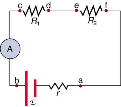
Schematic showing an ammeter correctly connected in series with a DC source and load so that the entire branch current flows through the meter. The same series placement is required when measuring charging or discharging current in a capacitor circuit. This figure also labels two resistors rather than a capacitor, but the connection rule for the ammeter is unchanged. Source.
Correct Use of Ammeters and Voltmeters
Place the ammeter in series with the capacitor–resistor branch.
Connect the voltmeter directly across the capacitor terminals.
Verify polarities for electrolytic capacitors, which can be damaged by incorrect orientation.
Ensure clean, secure contact points to minimise unwanted resistance.
During charging or discharging, the voltmeter reading changes smoothly. Observing this change allows identification of whether capacitors are combined in series or parallel based on overall capacitance effects.
Investigating Series Capacitor Arrangements
A series arrangement reveals how capacitors collectively respond when placed end-to-end in a single path.
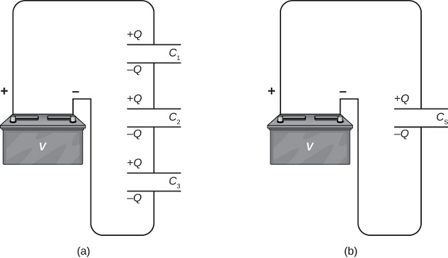
Diagram of three capacitors connected in series to a DC source, showing that each carries the same charge Q. An accompanying equivalent circuit represents the entire series string as a single capacitor CS, whose value is less than any individual capacitor. The figure also hints at the concept of equivalent capacitance CS, which is addressed in the dedicated series–parallel subsubtopics rather than in this practical-investigation section. Source.
The total capacitance is less than that of any individual capacitor in the series, meaning the measured potential differences and currents behave differently from a single-capacitor circuit.
EQUATION
—-----------------------------------------------------------------
Equivalent Capacitance (C) = 1 / (1/C₁ + 1/C₂ + …)
C = Equivalent capacitance in farads (F)
C₁, C₂ … = Individual capacitor values in farads (F)
—-----------------------------------------------------------------
When observing a series system:
The ammeter shows the same current through each capacitor because current is identical in a single continuous loop.
The voltmeter reveals that the supply potential difference divides across the capacitors in proportion to their capacitances.
Students may note that capacitors with smaller capacitances take a larger share of the total potential difference.
After setting up the circuit, students record steady-state voltmeter readings once the charging process is complete. These measurements help confirm the theoretical relationship between series capacitors and reduced total capacitance.
Investigating Parallel Capacitor Arrangements
Parallel investigations illustrate how combining capacitors side-by-side increases overall capacitance, enabling the system to store more charge at the same supply potential difference. This configuration is frequently encountered in practical electronics where large effective capacitance is desired.
EQUATION
—-----------------------------------------------------------------
Equivalent Capacitance (C) = C₁ + C₂ + …
C = Equivalent capacitance in farads (F)
C₁, C₂ … = Individual capacitor values in farads (F)
—-----------------------------------------------------------------
In a parallel setup:
The voltmeter reads the same potential difference across every capacitor because each branch connects directly to the supply.
The ammeter detects a greater charging current than in series arrangements, reflecting the increased total capacitance.
The increase in current and stored charge is observable when switching the supply on and off, particularly with larger parallel combinations.
Systematic measurement of p.d. and current allows students to confirm that the total capacitance is simply the sum of individual capacitances.
Recommended Procedure for Series and Parallel Measurements
To meet OCR expectations, students should follow a structured approach:
Construct the circuit carefully using a diagram as reference.
Confirm correct meter placement before energising the system.
Close the switch to allow the capacitor to charge and observe meter readings.
Open the switch and monitor discharging behaviour if required.
Take repeat measurements to reduce random errors.
Record voltage and current changes at key intervals.
Compare measured values with calculated predictions for total capacitance.
Maintaining consistency between trials is essential for producing reliable data.
Safety and Good Laboratory Practice
Capacitor investigations require awareness of safe limits and proper handling techniques. Students must:
Use low-voltage supplies to avoid damaging components.
Discharge capacitors safely using a resistor before altering circuit connections.
Handle electrolytic capacitors cautiously, observing polarity markings.
Avoid short circuits, which can cause rapid, uncontrolled capacitor discharge.
Keep leads tidy and connections secure to ensure accurate measurements.
Attention to safety ensures both reliable results and protection of equipment.
Practice Questions
Question 1 (2 marks)
A student sets up a circuit to investigate a single capacitor using an ammeter and a voltmeter.
Explain where the ammeter and voltmeter should be placed in the circuit to correctly measure the charging behaviour of the capacitor.
Question 1 (2 marks total)
1 mark: Ammeter stated to be placed in series with the capacitor–resistor branch.
1 mark: Voltmeter stated to be connected directly across the capacitor.
Question 2 (5 marks)
A practical investigation is carried out to compare the behaviour of two capacitors connected first in series and then in parallel.
The same DC supply, switch, ammeter, and voltmeter are used in both arrangements.
(a) Describe the steps the student should take to set up and carry out the investigation safely.
(b) Explain how the readings on the ammeter and voltmeter allow the student to identify the differences between the series and parallel arrangements.
(c) State what effect the two arrangements have on the total capacitance and justify your answer using observations from the investigation.
Question 2 (5 marks total)
(a) Safe setup and procedure (2 marks)
1 mark: States that the circuit must be built with the supply turned off, checking correct polarity for electrolytic capacitors.
1 mark: Mentions safe charging and discharging using a resistor and ensuring low-voltage supply is used.
(b) Using meter readings (2 marks)
1 mark: Identifies that the voltmeter shows the same p.d. across each capacitor in parallel but divided p.d. in series.
1 mark: Identifies that the ammeter reading is larger in the parallel arrangement due to greater total capacitance.
(c) Effect on total capacitance (1 mark)
1 mark: States that total capacitance is lower in series and higher in parallel, justified by observed p.d. distribution and charging current.
FAQ
A key technique is to use instruments with suitable ranges so that readings fall near the middle of the scale, reducing percentage uncertainty.
Use short, low-resistance connecting leads and ensure firm connections to minimise unwanted resistance that could affect charging behaviour.
Repeat measurements several times and take an average to reduce random error. Recording voltage changes at consistent time intervals also helps produce reliable, comparable results.
When the switch is closed, the capacitor initially behaves like a short circuit because there is no charge on its plates, producing a brief surge in current.
To measure this safely:
• Use a resistor in series to limit the maximum current.
• Ensure the ammeter has an appropriate upper range.
• Avoid rapidly switching the supply on and off, as this can stress both the capacitor and the meter.
Manufacturing tolerances mean real capacitors can differ by up to ±20% or more from their stated capacitance.
Temperature changes can slightly alter the dielectric properties, affecting capacitance. Loose or resistive connections in the test circuit may slow charging, giving the impression of a different capacitance.
Electrolytic capacitors may drift from their nominal value over time, especially if operated near their voltage limit.
Electrolytic capacitors contain a chemically formed dielectric layer that is stable only when the applied voltage has the correct polarity.
Reverse polarity can cause:
• Breakdown of the dielectric, leading to leakage current.
• Heating or swelling due to internal chemical reactions.
• Permanent damage or, in severe cases, rupture of the capacitor.
This is why polarity markings must be checked before energising the circuit.
A capacitor can be treated as fully charged when the voltmeter reading becomes steady and matches the supply voltage (or the share of it in series).
Additionally:
• The ammeter reading should fall to zero, indicating no further charging current.
• Disconnecting the supply should cause the capacitor to hold its voltage temporarily, verifying that charge has accumulated on the plates.
Small fluctuations can occur due to meter resolution, but a stable reading indicates effective full charge.
