
OCR Specification focus:
‘For capacitors in parallel: C = C1 + C2 + … ; explain effect on total capacitance.’
Capacitors connected in parallel combine to increase overall charge-storage capability, creating an effective capacitance larger than any individual capacitor and enabling flexible design of electronic circuits.
Understanding Parallel Combinations of Capacitors
Parallel capacitor arrangements are fundamental in circuit design because they allow engineers to tailor the overall capacitance—the ability of a component to store electric charge per unit potential difference. When connected in parallel, capacitors share the same potential difference (p.d.), yet each contributes independently to the storage of charge. This configuration contrasts with series arrangements and is particularly useful when a circuit requires a higher total capacitance or when components need to be added to fine-tune performance.
Capacitance: The ability of a capacitor to store charge per unit potential difference across its plates.
Parallel configurations are frequently employed in timing circuits, power smoothing networks, and energy-storage modules because they permit the designer to increase capacitance without exceeding physical space or voltage ratings of single capacitors.
Key Characteristics of Parallel Capacitor Circuits
When two or more capacitors are placed in parallel, their positive plates are connected together and their negative plates are connected together.
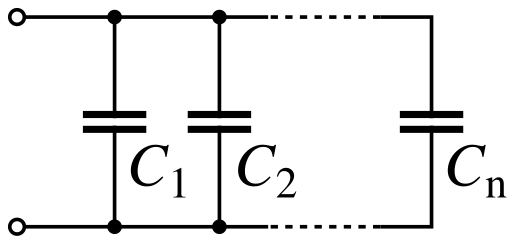
Three capacitors connected in parallel, each sharing the same potential difference while storing charge independently, showing why total capacitance increases in a parallel arrangement. Source.
This means every capacitor experiences the same p.d. across its plates, yet each one can accumulate charge independently depending on its capacitance value. The total stored charge in the circuit is therefore the sum of the charge stored on each individual capacitor.
In practical terms, this allows a combination of capacitors to act together as a single, larger capacitor within the circuit. The behaviour of the combination remains predictable because it follows a straightforward mathematical relationship.
Total Capacitance in Parallel
The specification emphasises the core rule governing parallel arrangements: the total capacitance is the sum of individual capacitances. This relationship makes parallel networks a simple and effective method for increasing charge storage.
EQUATION
—-----------------------------------------------------------------
Total Capacitance (C) = C1 + C2 + …
C = Total capacitance (farad, F)
C1, C2, … = Individual capacitances of each capacitor (farad, F)
—-----------------------------------------------------------------
This equation reflects the physical interpretation of each capacitor contributing extra plate area to the combination. Since capacitance is directly proportional to plate area, connecting capacitors in parallel effectively produces a larger total effective plate area, and therefore a greater ability to store charge.
Parallel combinations are therefore uniquely valuable in situations where a single capacitor cannot provide the required capacitance due to manufacturing limits, size constraints, or voltage compatibility issues. By selecting capacitors appropriately, designers can build a composite capacitance tailored to the needs of the circuit.
Why Total Capacitance Increases in Parallel
To understand the increase in total capacitance, it is helpful to consider the nature of charge movement within the circuit. When the capacitors are connected to a supply, electrons flow from the negative terminal towards the plates until each capacitor reaches equilibrium at the supply p.d. Because the capacitors share this same voltage, the total stored charge is simply the sum of charges each can hold.
A parallel arrangement does not alter the potential difference but allows more charge to accumulate overall. The effect resembles extending the surface area of a single capacitor while keeping the separation of plates and the applied voltage constant.
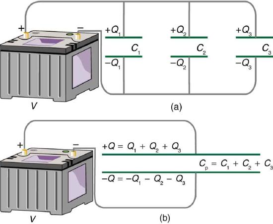
Diagram illustrating capacitors in parallel alongside their equivalent single capacitor, emphasising how effective plate area and total charge combine to give a larger total capacitance. Source.
The greater the total area available for charge storage, the larger the capacitance.
Practical Implications in Circuit Behaviour
Parallel capacitor networks offer several clear advantages:
Increased capacitance for energy storage: Connecting multiple capacitors allows circuits to store more energy, which is particularly beneficial in smoothing output from rectifiers or supporting short-duration power demands.
Capacitance fine-tuning: Small capacitors are often added in parallel with larger ones to adjust capacitance precisely to design requirements.
Voltage rating flexibility: Because every capacitor in parallel experiences the same p.d., designers can use capacitors with identical or compatible voltage ratings without risk of one being overstressed.
Enhanced filtering performance: In filters, parallel capacitors improve the ability to remove unwanted AC fluctuations by increasing the overall capacitive reactance at different frequencies.
After integrating capacitors in parallel, the circuit retains a stable voltage across each branch while offering increased capability for charge accommodation. This ensures predictable operation, making the configuration especially valuable in sensitive electronic applications.
Analysing Circuits Containing Parallel Capacitors
When analysing such circuits, it is essential to apply consistent principles:
Identify all capacitors sharing the same p.d. These are the capacitors in parallel.
Calculate total capacitance using the sum rule, ensuring all capacitances are in compatible units.
Determine total charge using Q = CV after computing the equivalent capacitance.
Consider current distribution: Although voltage is shared, charging current divides between capacitors according to their capacitances.
Assess energy storage: Since larger capacitance allows more energy to be stored, evaluate W using appropriate capacitor energy equations when required elsewhere in the course.
The ability to treat several capacitors as one equivalent component greatly simplifies analysis and assists students in understanding how charge distribution and storage operate at a circuit level.
Practice Questions
Question 1 (2 marks)
Two capacitors, 4.0 microfarads and 6.0 microfarads, are connected in parallel.
(a) State the rule for calculating total capacitance for capacitors connected in parallel.
(b) Calculate the total capacitance of the combination.
Question 1 (2 marks)
(a)
• States that total capacitance in parallel is the sum of individual capacitances. (1)
(b)
• Correct calculation: 4.0 microfarads + 6.0 microfarads = 10.0 microfarads. (1)
Question 2 (5 marks)
A circuit contains three capacitors connected in parallel: C1 = 2.0 microfarads, C2 = 3.0 microfarads, and C3 = 5.0 microfarads. The combination is connected across a constant potential difference.
(a) Explain why each capacitor in this arrangement has the same potential difference across it.
(b) Describe how the total charge stored by the combination relates to the charge on each individual capacitor.
(c) Using principles of parallel capacitor combinations, explain why the total capacitance increases when more capacitors are connected in parallel.
Question 2 (5 marks)
(a)
• States that all capacitors in parallel are connected directly across the same two points in the circuit. (1)
• Therefore they must experience the same potential difference. (1)
(b)
• States that total charge is the sum of charges stored on each capacitor. (1)
(c)
• Explains that each capacitor provides an additional charge-storage pathway. (1)
• Explains that combining capacitors in parallel effectively increases total plate area, so capacitance increases. (1)
FAQ
Parallel arrangements improve the circuit’s response to rapid voltage fluctuations because the increased total capacitance provides a larger reservoir of charge that can be released quickly.
This is particularly useful in power supply smoothing, where sudden dips in voltage can be compensated for by the additional stored charge.
Higher capacitance also reduces the size of transient voltage spikes, helping stabilise sensitive components.
Different capacitor types excel at different frequency ranges and behaviours. Combining them in parallel allows the strengths of each to be used simultaneously.
For example:
• Electrolytic capacitors provide high capacitance for low-frequency smoothing.
• Ceramic capacitors respond well to high-frequency noise.
Used together, they create a broader, more effective filtering response than either type alone.
Yes. When capacitors are connected in parallel, the effective ESR decreases because each capacitor provides an additional parallel path for current.
Lower ESR improves performance in applications requiring fast charge and discharge cycles, such as pulse circuits.
It also reduces heat generation, increasing component reliability.
The effect depends on the mode of failure.
• If it goes open-circuit, it simply stops contributing capacitance and the remaining capacitors continue functioning.
• If it goes short-circuit, it can bypass the supply and potentially damage components or blow a fuse.
Parallel networks therefore often include protective elements such as fuses or current-limiting resistors.
Even though all capacitors in parallel experience the same potential difference, each one must still be individually rated to withstand that voltage.
Exceeding a capacitor’s voltage rating risks dielectric breakdown, overheating, or catastrophic failure.
In practice, engineers usually select capacitors with a safety margin above the expected operating voltage to ensure long-term reliability.
