
OCR Specification focus:
‘Investigate charge and discharge using meters or data-loggers; outline safe practice and key steps.’
Measuring capacitor transients allows students to observe how current, potential difference, and charge vary during capacitor charging and discharging. This topic focuses on experimental methods using meters or data-loggers, emphasising accuracy, safety, and correct procedures essential for reliable investigation of capacitor behaviour.
Understanding Capacitor Transients
A capacitor transient refers to the short-duration change in electrical quantities when a capacitor undergoes charging or discharging. During this interval, measurable quantities vary non-linearly, making careful data capture essential. Investigating these transients provides evidence for exponential behaviour, verifies theoretical predictions, and strengthens understanding of capacitor–resistor circuits.
Key Measured Quantities
Students typically monitor three changing electrical properties:
Potential difference (p.d.) across the capacitor
Current in the charging or discharging loop
Charge stored on the capacitor, which may be inferred from p.d. measurements using an appropriate equation when required
Because these quantities change rapidly at the start of a transient, precise instrumentation and efficient data collection are important.
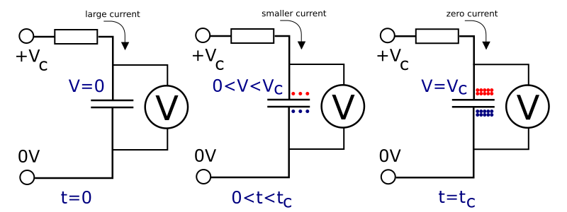
A pair of graphs showing how the current into a capacitor falls while the voltage across it rises as the capacitor charges. The diagram emphasises the steep initial gradients, where measurements must be closely spaced in time, and the gradual approach to steady values. The exact numerical labels and time-axis scaling extend beyond the minimum syllabus content but simply illustrate the same underlying charging behaviour students will observe experimentally. Source.
Essential Apparatus
A suitable circuit for transient measurements requires:
A capacitor of known capacitance, chosen so that the transient duration is long enough for effective measurement
A resistor to control the rate of charge and discharge
A switch, enabling clear start-and-stop control of each transient
Either analogue meters (an ammeter and voltmeter) or a data-logger with voltage and current sensors
Connecting leads with secure insulation and good conductivity
Low-voltage d.c. power supply, ensuring safe operation throughout the procedure
Reliable, low-resistance connections help ensure that measured values reflect the expected theoretical behaviour rather than circuit imperfections.
Setting Up the Circuit
A typical arrangement places the capacitor and resistor in series with the power supply and switch.
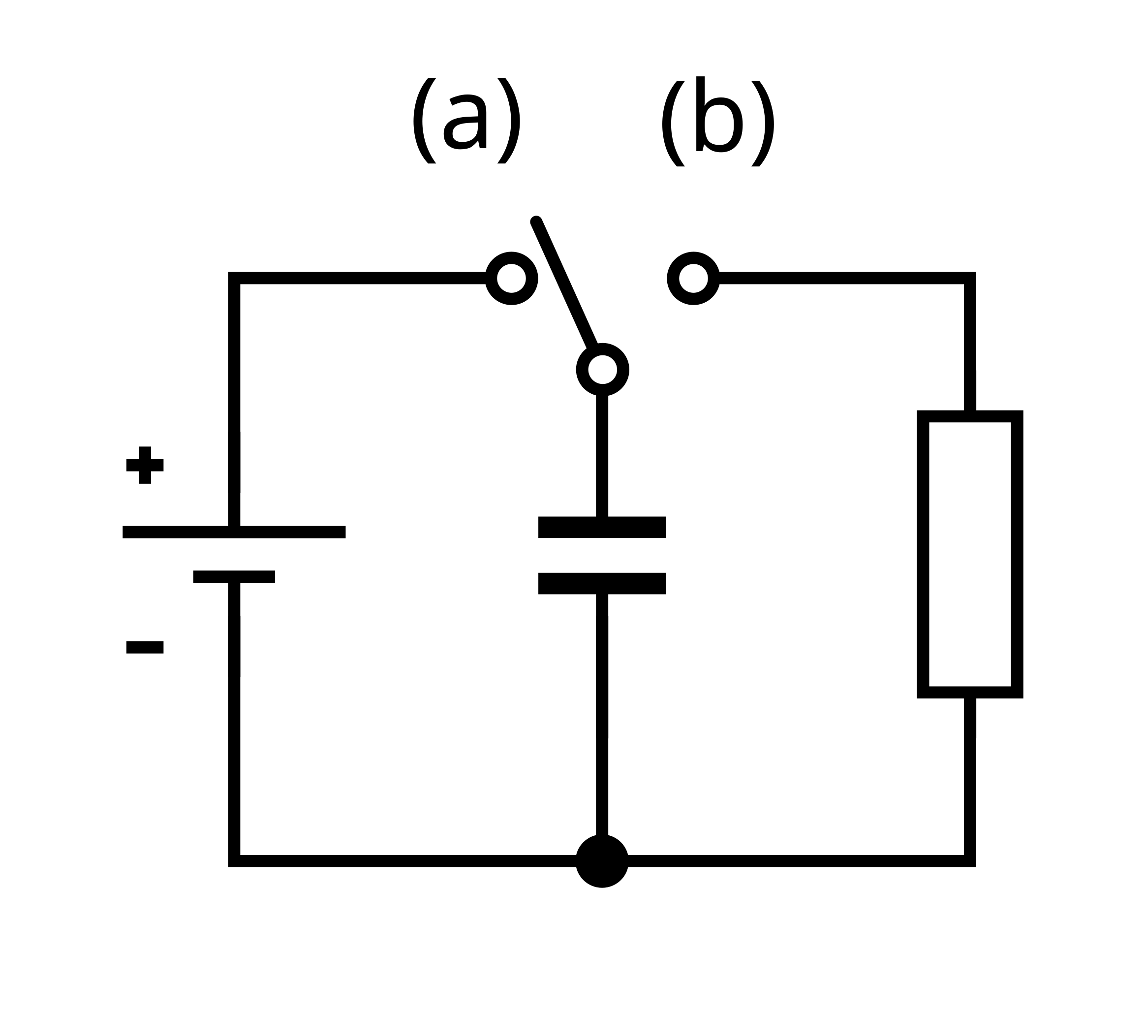
A simple RC circuit used to charge and discharge a capacitor through a resistor. The diagram shows a d.c. supply, a switch, a resistor, and a capacitor in series, matching the arrangement used when measuring transients in the laboratory. Any additional symbols simply label components and do not add content beyond the A-Level requirements. Source.
During charging, the switch connects the supply to the circuit. During discharging, the switch is moved so the capacitor is isolated from the supply and allowed to discharge through the resistor alone. This separation ensures uncontaminated discharge data.
Minimising Uncertainties
Several practical steps reduce measurement errors:
Use high-resolution digital meters or a data-logger, especially when currents change rapidly
Keep leads short to minimise stray resistance
Ensure meter polarities follow circuit conventions
Zero sensors or calibrate meters before starting measurements
Minor improvements in set-up can significantly improve the clarity of collected data.
Using Meters to Measure Transients
When using analogue or digital meters, the student typically records p.d. and current readings manually at regular intervals. However, because early changes in current are very fast, manual data collection tends to be coarse near the start of the transient.
Advantages and Limitations
Advantages: Accessible equipment, straightforward to understand, effective for learning fundamental measurement skills
Limitations: Slow manual reading leads to fewer data points; rapidly changing values may be missed; human reaction time increases uncertainty
Despite these limitations, meter-based investigations remain valuable for developing procedural competence.
Using Data-loggers to Measure Transients
A data-logger offers a far more detailed representation of capacitor behaviour.
Features and Benefits
Automatic high-frequency sampling, capturing rapid early changes accurately
Simultaneous current and p.d. recording, reducing time delays between readings
Direct digital storage, enabling rapid graphing and analysis
Consistent time-base, essential for comparing charging and discharging curves
Because data-loggers remove the need for manual timing, they reduce random error and offer clearer experimental evidence of exponential behaviour.
Selecting Appropriate Sampling Rates
For accurate transient measurement, the sampling rate should be high enough to capture changes near the beginning of the process. A recommended approach is:
Use several hundred samples per second for short time constants
Reduce sampling frequency for larger time constants to avoid excessive data volume
A brief test run can help determine whether the chosen setting adequately resolves the expected curve.
Conducting the Procedure
The general procedure for capturing transient data includes:
Ensuring the power supply is switched off before assembling the circuit
Connecting meters or sensors in the correct positions:
Voltmeter or voltage sensor parallel with the capacitor
Ammeter or current sensor in series
Setting data-logger parameters such as sampling rate and total recording time
Charging the capacitor fully by closing the circuit with the power supply connected
Starting the data-logger or preparing to take readings before initiating a transient
Opening or switching the circuit to begin discharging through the resistor
Allowing the capacitor to discharge completely before resetting the circuit for further trials
Repeating the experiment ensures reliable data and identifies anomalous readings.
Safe Practice When Investigating Transients
Although capacitor experiments in the A-Level laboratory are low risk, several safety principles apply:
Use low-voltage supplies, typically below 12 V
Ensure capacitors are not polarised types unless connected correctly, as incorrect polarity can cause damage
Avoid touching exposed conductors during operation
Allow capacitors to discharge fully before handling or modifying the circuit
Check component ratings, ensuring resistor power ratings are not exceeded
Safe experimental procedure protects both users and equipment.
Interpreting Recorded Data
Whether collected manually or digitally, transient data typically shows a characteristic curved profile.
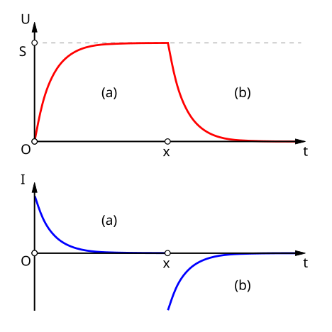
Graphs showing how capacitor voltage (upper graphs) and current (lower graphs) vary during charging (a) and discharging (b). The curves demonstrate the rapid initial change followed by a slower approach to a final value, mirroring the shapes seen in experimental data from meters or data-loggers. The labelled saturation point “S” and detailed percentage scales go slightly beyond the syllabus but simply provide extra clarity about how the curves level off. Source.
Students observe that the rate of change decreases over time, forming the foundation for later analysis using exponential equations. Reliable measurement is crucial for demonstrating this underlying mathematical structure and for validating predictions about capacitor behaviour during charging and discharging.
Practice Questions
Question 1 (2 marks)
A student investigates the discharge of a capacitor through a resistor using a data-logger.
State one advantage of using a data-logger rather than taking meter readings manually, and explain why this advantage is important for measuring capacitor transients.
Question 1 (2 marks)
Any one valid advantage (1 mark) from:
High sampling rate allows rapid changes at the start of the transient to be captured.
Automatic data collection reduces human error.
Simultaneous voltage/current measurements avoid timing inconsistencies.
Provides a consistent and precise time-base for the data.
Explanation of why this matters (1 mark), e.g.:
Early in the transient, values change very quickly, so frequent measurements are essential for accurate analysis.
Reducing timing or reading errors improves the reliability of plotted curves.
Question 2 (5 marks)
A capacitor of known capacitance is charged and then allowed to discharge through a resistor. The student uses a voltmeter connected across the capacitor and a data-logger to monitor the potential difference during discharge.
Describe the full experimental procedure the student should follow to obtain reliable discharge data. In your answer, include safe practice, the correct placement of measuring instruments, and the key steps required to ensure accurate and useful recorded measurements.
Question 2 (5 marks)
Award marks for the following points (any valid order):
1 mark:
States that the voltmeter (or voltage sensor) must be connected in parallel with the capacitor.
1 mark:
Identifies that the capacitor must first be fully charged before beginning the discharge measurement (e.g. closing the charging circuit).
1 mark:
States that the discharge should begin only after the data-logger is running or ready to record, ensuring no early data is missed.
1 mark:
Mentions at least one safe practice, such as:
Using a low-voltage supply (e.g. below 12 V).
Ensuring the capacitor is fully discharged before handling.
Checking polarity if using electrolytic capacitors.
Avoiding contact with exposed conductors.
1 mark (procedural accuracy):
Describes a key reliability step such as:
Selecting an appropriate sampling rate (sufficiently high for early rapid changes).
Repeating measurements to check for consistency.
Minimising stray resistance (short leads, secure connections).
FAQ
Internal resistance alters the effective resistance in the circuit, slightly changing the time constant and shaping the transient curve.
A voltmeter with high internal resistance has little effect, but a current sensor or ammeter with lower internal resistance increases total series resistance.
This can lead to:
Slower charging and discharging
Reduced peak current
Slight distortion in early rapid changes
To minimise impact, use sensors with appropriate specifications and keep all additional resistances predictable.
Non-polar capacitors (e.g. polyester, ceramic) function correctly when connected either way around because they are designed to withstand voltage in both directions.
Their symmetrical construction means:
No internal chemical reactions depend on polarity
No damage occurs if the polarity reverses during transient behaviour
They remain safe in rapid switching conditions typical of repeated charge–discharge cycles
This makes them ideal for educational transient experiments.
Sampling duration must be long enough to capture the entire decay.
A suitable duration depends on:
The time constant (RC), which determines how quickly the curve falls
The need to capture several multiples of RC for a full data set
Avoiding unnecessarily long recordings that create overly large files
A practical guideline is to record for at least 5RC, ensuring the capacitor has effectively reached zero potential difference.
Minor variations arise from physical and environmental factors that subtly affect circuit behaviour.
Common causes include:
Temperature changes altering resistance
Slight differences in switch timing
Contact resistance variations at terminals
Residual charge left in the capacitor before the next trial
These differences are normal and typically reduced by careful resetting and consistent experimental technique.
Stray capacitance is formed unintentionally by nearby conductors, cables, and circuit geometry.
Its effects include:
A small increase in the effective capacitance
Slightly longer discharge times
Smoother, less steep initial decay
Possible distortion in high-precision measurements
Good experimental practice—short leads, tidy layout, and avoiding parallel cable runs—helps minimise stray effects.
