
OCR Specification focus:
‘Outline techniques using search coils to investigate magnetic flux and induction.’
Search coils allow experimental investigation of changing magnetic flux by converting variations in magnetic fields into measurable induced e.m.f., providing a powerful method for probing electromagnetic induction with accuracy.
Search Coils and Their Purpose
A search coil is a small coil of wire used to measure magnetic flux or magnetic flux density within a region of a magnetic field.
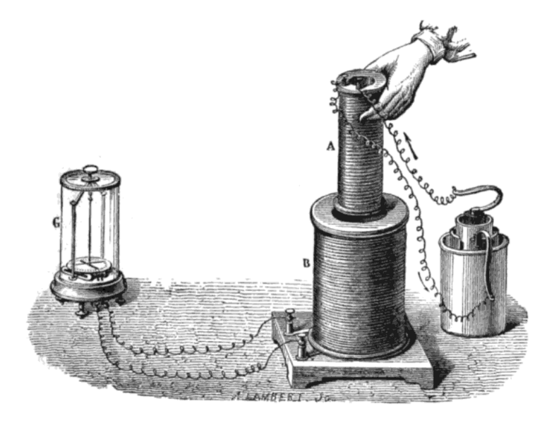
A historical diagram of Faraday’s induction experiment, showing a small current-carrying coil moved into and out of a larger coil connected to a galvanometer. As the magnetic flux through the larger coil changes, an induced current is detected. The image includes additional historical apparatus detail not required by the syllabus. Source.
Its operation relies on electromagnetic induction: when the magnetic flux through the coil changes, an e.m.f. is induced across its terminals. This makes the device ideally suited for examining how magnetic fields vary with time, position, or orientation.
Magnetic flux: The product of magnetic flux density, area, and the cosine of the angle between them.
A search coil is often connected to a voltmeter, data logger, or oscilloscope to record the induced e.m.f. Because the induced e.m.f. depends on the rate of change of flux, search coils provide a dynamic measurement tool rather than giving static field values directly.
Principles Underpinning Search Coil Measurements
At the heart of the technique is the relationship between induced e.m.f. and the rate of change of magnetic flux linkage.
EQUATION
—-----------------------------------------------------------------
Induced e.m.f. (𝓔) = − d(NΦ)/dt
𝓔 = Induced e.m.f. in volts
N = Number of turns on the search coil (no unit)
Φ = Magnetic flux through one turn, in webers
t = Time in seconds
—-----------------------------------------------------------------
This relationship shows that search coils respond to changes in flux rather than constant flux. Therefore, only time-varying fields or physically moved/rotated coils generate measurable signals. This dependence allows students to explore both steady magnetic fields through controlled movement and alternating fields directly.
A search coil’s sensitivity depends on its number of turns, cross-sectional area, and orientation. Increasing the number of turns or the area increases the total flux linkage, enhancing induced e.m.f. and improving measurement accuracy.
Construction and Design Considerations
Coil Structure
A typical search coil consists of:
A tightly wound solenoid of fine copper wire
A known number of turns (N)
A rigid former that maintains a fixed coil area
Insulated leads for connection to measuring instruments
Factors Affecting Sensitivity
Area of the coil: Larger area increases flux linkage.
Number of turns: More turns produce a proportionally larger induced e.m.f.
Resistance of the coil and connecting leads: Lower resistance helps reduce signal loss.
Orientation: Maximum flux linkage occurs when the plane of the coil is perpendicular to the magnetic field.
Magnetic flux linkage: The product of magnetic flux through a single turn and the number of turns on the coil.
After defining these aspects, it becomes easier to understand how search coils function in practical laboratory settings.
Techniques for Using Search Coils to Investigate Magnetic Flux
1. Measuring Flux by Rotating a Coil
One common approach is to rotate a search coil within a magnetic field:
The coil is mounted on an axle at the centre of the field region.
As the coil rotates, the enclosed magnetic flux continuously changes.
The induced e.m.f. can be monitored using an oscilloscope.
This method is particularly useful for investigating sinusoidal flux changes when rotation is uniform.
2. Inserting a Coil into a Varying Magnetic Field
Another widely used technique involves placing a stationary search coil into a region where the magnetic field varies with time:
The search coil is inserted into the core of an a.c. electromagnet.
When the flux through the electromagnet changes, an e.m.f. is induced in the coil.
The induced voltage waveform mirrors the flux variation and can be studied in detail.
This technique allows direct examination of the relationship between alternating magnetic fields and induced voltages.
3. Using Search Coils to Map Magnetic Fields
Search coils can be used to map how flux density changes across space:
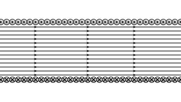
Diagram of a long, tightly-wound cylindrical coil producing an approximately uniform magnetic field inside. The magnetic field lines illustrate how flux passes through each turn of the coil. The diagram idealises the coil as infinitely long, which is slightly beyond the syllabus but still directly supportive of the concept. Source.
Move the coil incrementally through the magnetic field region.
Keep orientation constant to prevent unwanted angular variations.
Record induced e.m.f. at each position.
Convert induced e.m.f. values into flux density information using calibration data.
This provides a spatial profile of magnetic field strength and is especially valuable in solenoid or electromagnet analysis.
Calibration of Search Coils
To obtain accurate numerical measurements, search coils must be calibrated. Calibration involves comparing the induced e.m.f. generated in a known, well-controlled magnetic environment with the theoretical prediction.
Key Calibration Steps
Place the coil within a region where B is known precisely.
Apply a controlled, time-varying magnetic field.
Measure the induced e.m.f. for several field strengths or rates of change.
Plot induced e.m.f. against theoretical flux linkage to derive a consistent calibration factor.
This procedure ensures that subsequent experimental data obtained from unknown fields can be interpreted reliably.
Measuring a.c. Magnetic Fields
Search coils are especially effective for analysing alternating magnetic fields:
When linked to an oscilloscope, they display the induced voltage waveform.
The amplitude is proportional to the peak rate of change of flux.
The frequency of the waveform equals the frequency of the alternating field.
This ability to visualise alternating field characteristics makes search coils a vital tool for exploring electromagnetic induction experimentally.
Practice Questions
Question 1 (2 marks)
A student uses a small search coil connected to an oscilloscope to investigate a time-varying magnetic field inside an electromagnet.
Explain why an e.m.f. is induced in the search coil only when the magnetic flux through it is changing.
Question 1 (2 marks)
1 mark: States that an e.m.f. is induced when magnetic flux through the coil changes (Faraday’s law).
1 mark: Explains that no e.m.f. is induced when the flux is constant because there is no change in flux linkage.
Question 2 (5 marks)
A technician places a search coil with 200 turns into the core of a solenoid carrying an alternating current. The search coil is connected to an oscilloscope, which displays a sinusoidal voltage trace.
(a) Describe how the arrangement allows the technician to investigate the changing magnetic flux in the solenoid.
(b) Explain how the technician could calibrate the search coil so that accurate values of flux density can be obtained from the oscilloscope readings.
(c) State how the oscilloscope trace would change if the frequency of the alternating current in the solenoid were increased.
Question 2 (5 marks)
(a) (2 marks)
1 mark: States that the alternating current in the solenoid produces a changing magnetic flux through the search coil.
1 mark: States that this changing flux induces a sinusoidal e.m.f. that can be observed on the oscilloscope.
(b) (2 marks)
1 mark: Describes placing the search coil in a region of known magnetic flux density or known rate of change of flux.
1 mark: States that comparing the induced e.m.f. with the known flux conditions allows a calibration factor to be established.
(c) (1 mark)
1 mark: States that the frequency of the oscilloscope trace would increase (waves become closer together).
FAQ
The coil can be very small, but reducing its size lowers the total flux linkage, making the induced e.m.f. weaker and potentially harder to measure.
To remain effective, a small search coil typically needs:
A relatively high number of turns
Low-resistance wiring
An amplification or sensitive measurement device
Miniature coils are useful for high-resolution spatial mapping, but they must be carefully calibrated due to their reduced signal strength.
Magnetic flux depends on the component of the magnetic field perpendicular to the coil’s area. If the coil rotates even slightly, the effective area through which flux passes changes.
This can lead to:
Underestimating flux when the coil is not perpendicular to the field
Inconsistent readings during field mapping
Increased uncertainty unless alignment is controlled rigorously
Stable mechanical mounting is essential for precise flux measurements.
At high frequencies, the induced e.m.f. changes rapidly, placing demands on both the coil and the measuring equipment.
Challenges include:
Increased reactance in the coil, reducing signal fidelity
Oscilloscope bandwidth limitations
Potential phase shifts between the actual flux changes and displayed waveform
Using low-inductance coils and high-bandwidth measurement devices helps maintain accuracy.
A solenoid driven by a known current produces a predictable and uniform magnetic field, allowing flux changes to be controlled precisely.
Permanent magnets:
Have non-uniform fields
May lose magnetisation over time
Provide no direct way to control flux rate
Solenoids therefore allow repeatable, calculable conditions that improve the accuracy of calibration.
The induced e.m.f. increases with both frequency and rate of change of magnetic flux, but practical boundaries exist.
Limiting factors include:
The voltage rating of the coil insulation
The safe input range of the measuring device
Heating in the coil due to induced currents
Risk of electrical noise or signal distortion at high voltages
Engineers ensure safety by selecting appropriate coil materials and using attenuators or protective circuits when necessary.
