
OCR Specification focus:
‘Use ideal transformer relations Vp/Vs = Np/Ns and Ip/Is = Ns/Np; describe experimental investigations.’
Transformers are essential electromagnetic devices used to change alternating potential differences efficiently, relying on mutual induction and controlled magnetic flux linkage within laminated iron cores across primary and secondary windings.
Transformer Operating Principles
Transformers function only with alternating current (a.c.), because an a.c. supply continually changes the magnetic flux in the core and therefore induces an electromotive force (e.m.f.) in the secondary coil. When the primary coil is connected to an a.c. source, the alternating current creates a continually varying magnetic flux in the laminated iron core. This magnetic flux links both the primary and secondary windings, ensuring that energy transfer occurs via mutual induction, the physical process by which a changing magnetic field induces an e.m.f. in another coil.
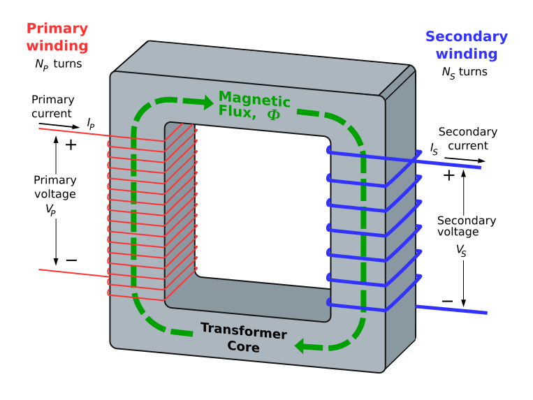
A three-dimensional illustration of an ideal single-phase transformer showing primary and secondary coils, magnetic flux flow, and the closed iron core path. This supports understanding of mutual induction and ideal transformer behaviour. The explicit flux path is more detailed than required but enhances visual comprehension. Source.
The core is typically made of thin insulated iron laminations to reduce eddy current heating and thus increase efficiency. Efficient flux linkage is achieved by winding the coils on opposite sides of a closed magnetic loop, ensuring that almost all magnetic flux produced by the primary coil passes through the secondary coil.
Ideal Transformer Relations
The OCR specification requires knowledge of the two core mathematical relations for an ideal transformer, where all magnetic flux is perfectly linked and no energy losses occur.
EQUATION
—-----------------------------------------------------------------
Transformer Voltage Relation (Vp/Vs) = Np/Ns
Vp = Primary potential difference (voltage), measured in volts
Vs = Secondary potential difference (voltage), measured in volts
Np = Number of turns on the primary coil
Ns = Number of turns on the secondary coil
—-----------------------------------------------------------------
This equation shows that the ratio of voltages is equal to the ratio of turns. A transformer with more turns on the secondary than the primary is a step-up transformer, while the opposite configuration is a step-down transformer. These ideas underpin how transformers adapt voltages for transmission or appliance use.
A transformer’s power transfer under ideal conditions follows from the assumption of 100% efficiency, so input power equals output power.
EQUATION
—-----------------------------------------------------------------
Current Ratio Relation (Ip/Is) = Ns/Np
Ip = Primary current, measured in amperes
Is = Secondary current, measured in amperes
Ns = Number of turns on the secondary coil
Np = Number of turns on the primary coil
—-----------------------------------------------------------------
The inverse relationship between current and turns ratio reflects conservation of energy in an ideal transformer. Step-up transformers increase voltage but decrease current; step-down transformers decrease voltage but increase current. This is essential for efficient power distribution, where high voltages and low currents minimise energy loss in cables.
A full understanding of these relations enables students to interpret how coil design directly shapes transformer performance and behaviour in practical circuits.
Construction Features Supporting Efficient Operation
The structure of a transformer is deliberately designed to maximise induced e.m.f. while minimising energy losses. Important features include:
Laminated iron core to reduce eddy currents
Soft iron material to enhance magnetic permeability
Tightly wound coils for strong magnetic coupling
Insulation between laminations and coil layers to prevent short circuits
Closed-loop core geometry to ensure effective flux linkage
These features enhance efficiency but do not alter the ideal transformer relations; instead, they help practical transformers approach ideal behaviour more closely.
Energy Loss Mechanisms in Real Transformers
Although the OCR syllabus focuses on ideal transformers, understanding real-world inefficiencies helps contextualise the need for design strategies. Key sources of loss include:
Eddy current heating in the core
Hysteresis loss from repeated magnetisation cycles
Resistance heating (I²R losses) in coils
Leakage flux, where some magnetic flux does not link both coils
Design choices such as ferrite cores, laminated sheets, and thicker wire help mitigate these losses.
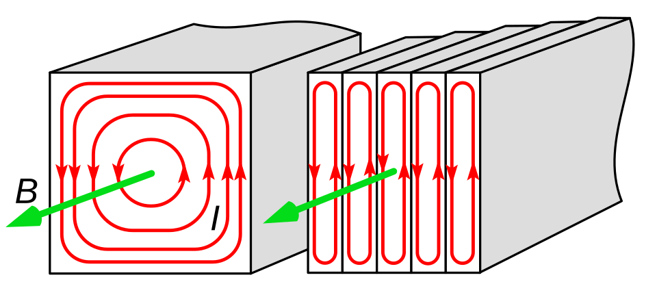
A diagram illustrating how laminating the core breaks up eddy-current loops and reduces heating. This visual supports understanding of energy-loss mechanisms in real transformers. The additional depiction of current loops goes slightly beyond the OCR requirement but remains helpful for conceptual clarity. Source.
A normal sentence here helps maintain clarity before progressing to required experimental investigations.
Experimental Investigations of Transformer Behaviour
The OCR specification requires students to be able to describe experimental investigations into transformers. These investigations aim to explore voltage ratios, flux linkage, and efficiency under varying conditions. Students typically examine how changing the number of turns or altering load conditions influences transformer performance.
Core Experimental Approaches
Common investigative procedures include:
Measuring Vp and Vs while varying the number of secondary turns
Recording currents in both windings to verify the current ratio relationship
Observing how coil arrangement affects flux linkage
Examining temperature rise to infer energy losses
Testing transformer behaviour with different load resistances
Such investigations frequently use low-voltage laboratory a.c. supplies for safety.
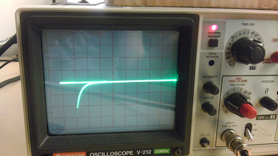
A photograph of an oscilloscope displaying the alternating output waveform from a transformer. This supports understanding of how waveform measurements form part of transformer investigations. The image focuses on measurement rather than the full setup, emphasising the analysis stage of the experiment. Source.
Investigating Efficiency and Load Dependence
Transformers behave differently under load. Experimental setups may involve:
Connecting variable resistances to the secondary coil
Monitoring voltage drop and current changes
Assessing energy loss by comparing VpIp and VsIs
Investigating how core material or lamination affects heating
These observations help demonstrate why practical transformers operate near, but never exactly at, ideal efficiency.
Practical Considerations for Safe and Accurate Measurements
To produce reliable data, students should ensure:
Accurate voltmeters and ammeters are placed appropriately in each circuit
Coils are fully insulated and securely mounted
The a.c. supply is stable
Heating is monitored to prevent damage
Magnetic flux leakage is minimised by correct coil placement on the core
These considerations reinforce the connection between theoretical relations and practical transformer behaviour, fulfilling the OCR requirement to describe experimental investigations.
Practice Questions
Question 1 (2 marks)
A transformer has 450 turns on its primary coil and 150 turns on its secondary coil.
State whether this transformer is step-up or step-down and explain your answer.
Question 1 (2 marks)
• Identifies it as a step-down transformer (1 mark)
• Explanation: secondary coil has fewer turns than the primary coil / Ns < Np (1 mark)
Question 2 (5 marks)
A student investigates a transformer using a low-voltage a.c. supply, an ammeter, a voltmeter, and a variable load resistor connected to the secondary coil.
Describe how the student could use this apparatus to verify both the transformer voltage ratio and current ratio relations.
Your answer should include:
• the measurements required
• how results would be compared with the theoretical ideal transformer equations
• any practical considerations needed to ensure reliable data.
Question 2 (5 marks)
• Measure the primary and secondary voltages using the voltmeter while the transformer is operating (1 mark)
• Compare measured Vp/Vs with the turns ratio Np/Ns to check the voltage relation (1 mark)
• Measure the primary and secondary currents with the ammeter when a load resistor is connected (1 mark)
• Compare measured Ip/Is with Ns/Np to check the current ratio relation (1 mark)
• Notes at least one valid practical consideration, e.g. keeping the a.c. supply constant, using a low-voltage supply for safety, ensuring good electrical connections, allowing for heating effects, or minimising flux leakage (1 mark)
FAQ
Real transformer efficiency depends mainly on minimising core, copper, and leakage losses.
Core losses arise from hysteresis and eddy currents. Using high-permeability, low-carbon iron and thin laminations helps reduce these losses.
Copper losses depend on the resistance of the windings.
• Thicker wire
• Shorter windings
• Better cooling
all help lower resistive heating.
Leakage flux can be reduced by careful coil placement and tightly coupling the windings around the core.
A d.c. supply produces a constant current and therefore a constant magnetic flux. Without a changing flux, no induced e.m.f. appears in the secondary coil.
Additionally, applying d.c. to the primary causes:
• rapid heating due to high current
• magnetic saturation of the core
• potential damage to insulation
These effects make d.c. operation unsafe and ineffective for transformers.
The geometry of the magnetic core affects flux linkage and energy losses.
Closed-loop shapes such as toroidal and E-I cores minimise leakage flux because they guide magnetic flux along a well-defined path.
Toroidal cores offer:
• low stray fields
• high efficiency
• compact design
but are more difficult to wind.
E-I cores are easier to manufacture and assemble, making them common in educational and industrial applications.
When the secondary coil is connected to a load, current flows, creating its own magnetic field that opposes the primary flux.
To maintain magnetic flux balance, the primary coil draws additional current from the supply. This extra current ensures that the primary magnetic field is sufficient to support both:
• the changing flux linking the coils
• the energy transferred to the load
This explains why input current depends on output demand, even though the coils are electrically isolated.
Safety measures reduce the risk of electric shock, overheating, and equipment damage.
Essential precautions include:
• using low-voltage a.c. supplies (typically 1–12 V)
• ensuring all exposed conductors are insulated
• avoiding prolonged operation under heavy load to prevent overheating
• securing coils and cores to prevent movement
• keeping measuring instruments rated for the expected voltages and currents
Maintaining clear workspace boundaries also helps prevent accidental contact with live circuits.
