
OCR Specification focus:
‘Describe construction and operation of a simple a.c. generator producing alternating e.m.f.’
A simple a.c. generator converts mechanical energy into electrical energy by rotating a coil in a magnetic field, producing a continuously changing and alternating e.m.f. suitable for power generation.
Structure and Purpose of a Simple A.C. Generator
A simple alternating current (a.c.) generator is a device designed to produce an alternating e.m.f. through the interaction of a rotating coil and a magnetic field. Its design reflects the essential requirement of electromagnetic induction: a changing magnetic flux linkage is needed to induce an e.m.f. This subsubtopic focuses solely on the construction of the generator and the principles governing its operation, directly reflecting the OCR specification.
Key Components
A basic a.c. generator contains several essential features, each contributing to the generation of an alternating output:
Coil (Armature)
The coil is typically rectangular and made from conducting wire. It is rotated within a magnetic field to ensure continual change in magnetic flux.Magnets or Electromagnets
These create a strong, uniform magnetic field through which the coil rotates. A consistent field enhances the induced e.m.f.Rotating Mechanism
Mechanical energy is supplied—often by a turbine or hand crank—to rotate the coil at constant angular speed.Slip Rings
These maintain electrical contact with the rotating coil while allowing it to turn freely, ensuring that the output voltage alternates rather than remaining unidirectional.Carbon Brushes
These press against the slip rings to transfer the induced e.m.f. to the external circuit with minimal friction.
These elements work together to produce a clean alternating voltage waveform that rises, falls, and reverses direction as required for a.c. applications.
Electromagnetic Induction in the Generator
The operating principle of a simple a.c. generator is based on Faraday’s law of electromagnetic induction, which states that an e.m.f. is induced when the magnetic flux linking a circuit changes. As the coil rotates, its orientation relative to the magnetic field continually varies, creating a repeating pattern of flux change.
Magnetic Flux Change During Rotation
During rotation:
The coil experiences maximum flux linkage when its plane is perpendicular to the magnetic field.
The flux linkage decreases smoothly to zero as the coil reaches a position parallel to the field.
Continued rotation reverses the direction of the flux, creating a negative maximum.
This sinusoidal variation underpins the production of an alternating e.m.f. and explains why the output voltage oscillates.
Induced E.M.F. in a Rotating Coil
When a rotating coil experiences a changing flux linkage, an alternating e.m.f. arises. The mathematical expression capturing this relationship is a cornerstone of generator theory and is appropriate for inclusion at this level.
EQUATION
—-----------------------------------------------------------------
Induced E.M.F. (𝓔) = − d(NΦ)/dt
N = Number of turns on the coil (no unit)
Φ = Magnetic flux through one turn (weber, Wb)
𝓔 = Induced e.m.f. (volt, V)
—-----------------------------------------------------------------
The negative sign reflects Lenz’s law, indicating that the induced e.m.f. opposes the change producing it. This opposition ensures energy conservation and provides the characteristic alternating nature of the output.
The equation shows that the induced e.m.f. depends on:
The number of turns on the coil
The strength of the magnetic field
The area of the coil
The angular speed of rotation
Only after the learner understands this relationship can they appreciate how generator design maximises output through physical and mechanical optimisation.
How the Alternating Output Is Produced
The behaviour of the slip rings and brushes is fundamental in determining the alternating nature of the output voltage. Unlike d.c. generators, which use a commutator to reverse connections periodically, the slip rings in an a.c. generator maintain a continuous connection but allow the polarity of the induced e.m.f. to reverse naturally as the coil rotates.
Sequence of Operation
Rotation begins: Mechanical input drives the coil through the magnetic field.
Flux linkage changes: Relative orientation between coil and field alters continuously.
E.M.F. peaks: When the coil sides cut the magnetic field lines most effectively, the induced e.m.f. reaches a maximum.
Polarity reverses: After half a turn, the direction of induced current reverses naturally.
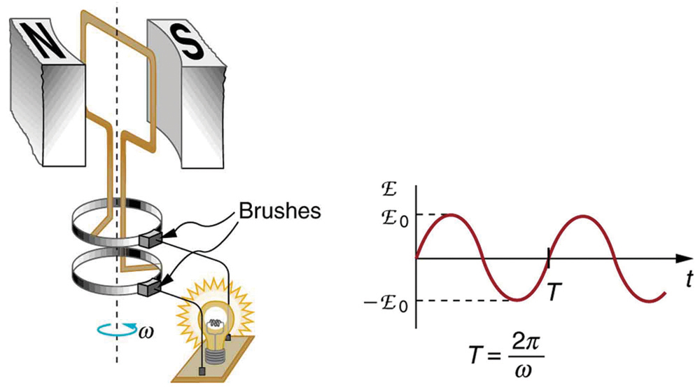
A simple a.c. generator with a rectangular coil rotating between the poles of a permanent magnet, connected to an external circuit by slip rings and brushes. The graph shows the sinusoidal variation of induced e.m.f. as the coil rotates. The period expression shown is additional detail and not required for this OCR subtopic. Source.
Continuous alternating output: This cycle repeats for every full revolution, producing a sinusoidal a.c. waveform.
The simplicity of this arrangement makes the a.c. generator an efficient and reliable method for large-scale electricity production.
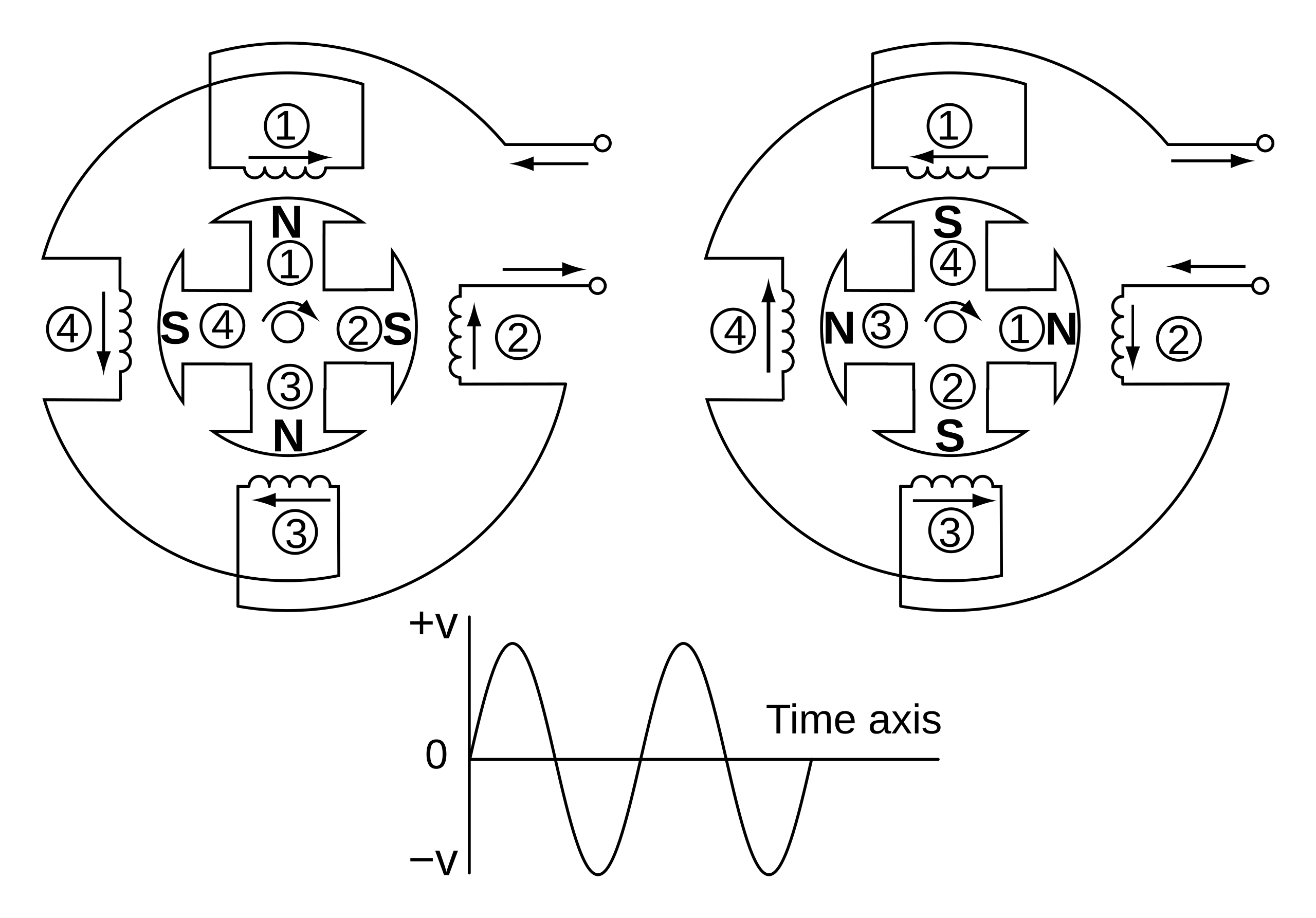
Diagram of a single-phase alternator showing a multipole field system and several stator coils connected to slip rings and brushes. All coils are arranged to produce a single alternating voltage. The additional detail of four poles and multiple coils illustrates real alternators and is beyond OCR’s required model. Source.
Practical Considerations in A.C. Generator Design
Although the underlying principle is simple, real generators employ specific strategies to maximise output:
Increasing coil turns enhances induced e.m.f.
Using stronger magnetic fields boosts flux linkage changes.
Rotating the coil at higher angular speeds increases the rate of change of flux.
Employing iron cores within coils concentrates magnetic flux.
These refinements ensure that even a basic generator configuration can produce substantial and useful alternating voltages.
Practice Questions
Question 1 (2 marks)
A student rotates a rectangular coil at constant speed in a uniform magnetic field to generate an alternating e.m.f.
Explain why the e.m.f. produced varies sinusoidally.
Mark Scheme:
• Coil’s orientation relative to the magnetic field changes continuously / flux linkage changes smoothly. (1)
• Rate of change of flux varies sinusoidally with angle of rotation, so induced e.m.f. follows a sine-like pattern. (1)
Question 2 (5 marks)
A simple a.c. generator consists of a rectangular coil rotating between the poles of a permanent magnet. Slip rings and carbon brushes connect the coil to an external circuit.
Describe how an alternating e.m.f. is generated in the coil and explain the roles of the slip rings and brushes in the operation of the generator.
Mark Scheme:
• Rotation of the coil changes the magnetic flux linking the coil. (1)
• Changing flux induces an e.m.f. according to Faraday’s law. (1)
• Direction of the induced e.m.f. reverses every half-turn because the coil sides cut the field lines in opposite directions. (1)
• Slip rings maintain continuous electrical contact with the rotating coil without reversing the connection. (1)
• Carbon brushes transfer the induced e.m.f. from the slip rings to the external circuit with minimal friction. (1)
FAQ
Soft iron cores concentrate and guide magnetic flux so that more field lines pass through the rotating coil. This increases the rate of change of flux and therefore increases the induced e.m.f.
In addition, soft iron reduces energy losses because it magnetises and demagnetises easily as the coil rotates, improving overall efficiency without altering the basic operating principle.
The frequency depends solely on the rotational speed of the coil. One full rotation produces one full cycle of alternating e.m.f.
For a generator driven by a turbine or motor:
• Faster rotation increases the frequency.
• Slower rotation decreases the frequency.
This is why large generators are connected to carefully regulated turbines to maintain stable supply frequencies.
Slip rings must maintain consistent, low-resistance contact with the brushes. Any irregularity causes fluctuating resistance, producing voltage noise or intermittent output.
Smoother surfaces also reduce abrasion on brushes, decreasing wear and limiting maintenance, which is important even in small laboratory-scale generators.
Several engineering limits prevent indefinitely increasing the induced e.m.f.:
• Maximum feasible magnetic field strength
• Heating of the coil as current flows
• Mechanical strain on the rotating shaft at high speeds
• Electrical insulation limits inside the coil windings
These constraints mean that voltage output cannot increase beyond practical material and design thresholds.
Multiple coils allow smoother output and greater efficiency. With several coils placed at different angles, the combined output reduces fluctuations and increases average power.
This arrangement also:
• Minimises mechanical vibration
• Allows higher total induced e.m.f.
• Provides redundancy, making the generator more reliable
Although more complex, the underlying induction principle remains identical to the simple single-coil model.
