
OCR Specification focus:
‘Define stress and strain; interpret ultimate tensile strength and failure points for materials.’
Stress and strain describe how materials respond to applied forces, revealing their strength and elasticity. Understanding these quantities allows physicists to predict material performance under different loading conditions.
Stress, Strain and Material Response
When a force acts on a material, it may deform — stretch, compress, or twist depending on the load and structure. To compare how different materials behave, physicists use stress and strain, which normalise force and deformation, removing dependence on size or shape.
Stress
Stress: The force per unit cross-sectional area acting on a material when a load is applied.
EQUATION
—-----------------------------------------------------------------
Stress (σ) = F / A
F = Force applied (newton, N)
A = Cross-sectional area (square metre, m²)
—-----------------------------------------------------------------
Stress measures the internal forces distributed across a material’s section. It allows comparison between materials of differing sizes under similar loads. Stress is measured in pascals (Pa) or newtons per square metre (N m⁻²).
When a tensile force pulls the material apart, tensile stress occurs. When a compressive force pushes it together, compressive stress occurs.
Strain
Strain: The ratio of the change in length to the original length of a material when subjected to stress.
EQUATION
—-----------------------------------------------------------------
Strain (ε) = ΔL / L
ΔL = Extension or compression (metre, m)
L = Original length (metre, m)
—-----------------------------------------------------------------
Strain is a dimensionless quantity since it compares two lengths. It shows how much a material deforms relative to its original size.
When a tensile load is applied, the strain is positive (elongation); under compression, the strain is negative (shortening).
Elastic and Plastic Behaviour
When stress is applied to a material, it deforms. The relationship between stress and strain defines whether the material behaves elastically or plastically.
Elastic deformation: The material returns to its original shape once the stress is removed. This occurs when the applied stress is within the elastic limit.
Plastic deformation: Permanent change in shape occurs after the elastic limit is exceeded. The atomic structure rearranges, and the material does not recover its original form.
In the elastic region, atoms are slightly displaced from their equilibrium positions but return when the force is removed. Beyond this, in the plastic region, atomic bonds break and reform in new positions.
The Stress–Strain Relationship
When a gradually increasing load is applied to a material sample (such as a wire or bar), the relationship between stress and strain can be plotted as a stress–strain graph. This graph provides rich information about the mechanical properties of the material.
A stress–strain graph plots engineering stress on the vertical axis against engineering strain on the horizontal axis for a tensile test specimen.
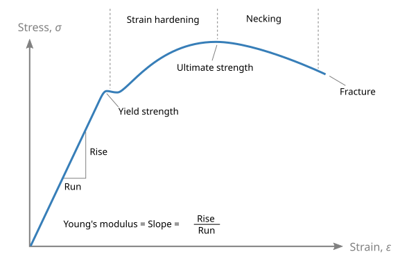
Typical engineering stress–strain curve for a ductile metal. The diagram labels the elastic region, yield, ultimate tensile strength (maximum engineering stress), and fracture. Axes and key points are explicit and uncluttered, matching OCR expectations. Source.
Key Features of the Stress–Strain Graph
Linear region: Stress is directly proportional to strain — this region obeys Hooke’s law.
Elastic limit: The highest stress where the material still returns to its original length once unloaded.
Yield point: The stress at which the material begins to deform plastically.
Plastic region: Deformation continues even without further increase in stress.
Ultimate tensile strength (UTS): The maximum stress the material can withstand before weakening.
Fracture point: The point at which the material finally breaks.
Each section reflects different atomic-level behaviours. In metals, after yielding, the dislocations in the atomic lattice begin to move, leading to necking and eventual fracture.
Ultimate Tensile Strength (UTS)
Ultimate Tensile Strength (UTS): The maximum stress a material can sustain before it begins to weaken and fracture.
EQUATION
—-----------------------------------------------------------------
Ultimate Tensile Strength (σₘₐₓ) = Fₘₐₓ / A
Fₘₐₓ = Maximum force before failure (newton, N)
A = Original cross-sectional area (square metre, m²)
—-----------------------------------------------------------------
The UTS reflects a material’s resistance to breaking under tension. A higher UTS indicates that the material can withstand greater loads before failure, making it stronger.
For example:
Steel has a high UTS, meaning it is strong and resists deformation.
Copper and aluminium have lower UTS values but greater ductility, allowing more plastic deformation before breaking.
UTS is typically measured experimentally using a tensile test machine, which records the stress–strain curve as a specimen is stretched until it fractures.
The ultimate tensile strength (UTS) is the peak engineering stress on the stress–strain curve, reached just before necking begins.
Failure Points and Fracture Behaviour
After the ultimate tensile strength is reached, further deformation causes the cross-sectional area to decrease rapidly — a process known as necking. Stress concentrates at this narrowed region until the material fails.
In ductile metals, fracture is preceded by necking and produces the characteristic cup-and-cone fracture surface.
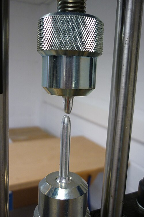
Photograph of a ductile tensile fracture showing cup-and-cone morphology in a cylindrical specimen after a uniaxial tensile test. This appearance results from void nucleation and coalescence within the necked region after the UTS has been reached. The image is a clear, high-resolution real-world complement to the schematic curve. Source.
Types of Material Failure
Ductile failure:
The material undergoes significant plastic deformation before breaking.
A visible neck forms.
Common in metals such as copper and mild steel.
Brittle failure:
The material fractures suddenly with little or no plastic deformation.
Common in ceramics, glass, and cast iron.
Failure occurs soon after reaching the elastic limit.
Polymeric behaviour:
Polymers may show a combination of ductile and elastic behaviour depending on temperature and strain rate.
Some, like rubber, can extend enormously before breaking.
The failure point represents the limit of a material’s usefulness in structural applications. Engineers select materials based on whether ductility or brittleness is advantageous for safety and design.
Practical Interpretation in Engineering and Physics
Understanding stress, strain, and ultimate tensile strength enables engineers to design safe and efficient structures.
Key practical applications include:
Determining whether a bridge cable or aircraft component can withstand operational loads.
Predicting how materials will behave under varying conditions such as heat or fatigue.
Selecting materials for applications requiring either flexibility or rigidity.
By analysing the stress–strain behaviour, materials scientists can balance strength, ductility, and stiffness, ensuring performance aligns with real-world demands.
In essence, these parameters form the foundation of mechanical material science, linking microscopic atomic interactions to macroscopic engineering performance.
Practice Questions
Question 1 (2 marks)
Define the terms stress and strain as used in the study of materials.
Mark scheme:
1 mark for correctly defining stress as force per unit cross-sectional area (1)
1 mark for correctly defining strain as the ratio of change in length to original length (1)
Question 2 (5 marks)
A metal wire of original length 2.0 m and cross-sectional area 1.5 × 10⁻⁶ m² is subjected to a gradually increasing tensile load.
The graph of stress against strain for this wire is linear up to a stress of 2.0 × 10⁸ Pa, beyond which it begins to curve.
It eventually fractures at a stress of 4.0 × 10⁸ Pa.
(a) State what is meant by the elastic limit and ultimate tensile strength of the material. (2 marks)
(b) Explain, using the graph information, how the material’s behaviour changes beyond the elastic limit up to the point of fracture. (3 marks)
Mark scheme:
(a)
1 mark for stating that the elastic limit is the maximum stress for which the material returns to its original shape when the load is removed (1)
1 mark for stating that the ultimate tensile strength is the maximum stress a material can withstand before it begins to weaken and eventually fracture (1)
(b)
1 mark for stating that beyond the elastic limit, the material deforms plastically and does not return to its original length (1)
1 mark for identifying that as stress increases further, necking occurs and cross-sectional area decreases (1)
1 mark for explaining that the material ultimately fractures when the stress exceeds its ultimate tensile strength (1)
FAQ
The ultimate tensile strength (UTS) depends on several factors, including:
Material composition: Alloys or impurities can strengthen or weaken atomic bonds.
Temperature: Higher temperatures generally lower UTS as atomic vibrations reduce bond strength.
Crystal structure and defects: Dislocations or grain boundaries affect how easily atoms move past each other.
Strain rate: Rapid loading can increase apparent strength since there’s less time for deformation processes.
In industrial testing, UTS is measured under controlled conditions because environmental and processing factors can significantly influence the result.
Stress measures force per unit area, so it carries physical units (N m⁻² or Pa).
Strain, however, is the ratio of extension to original length — two quantities with the same unit (metres). When these are divided, the units cancel, leaving strain dimensionless.
This means that strain represents relative deformation, not an absolute value. For instance, a strain of 0.01 indicates a 1% change in length, independent of the material’s size or units used.
The ultimate tensile strength (UTS) is the maximum stress a material can sustain before necking starts.
The breaking stress, on the other hand, occurs at the point of fracture, after the material has already weakened and the cross-sectional area has reduced significantly.
Because the area is smaller at fracture, the breaking stress (based on the original area) is often lower than the UTS. This distinction helps engineers design components that fail safely, before catastrophic breakage occurs.
During plastic deformation, atoms move irreversibly from their original lattice positions through the movement of dislocations — small defects in the crystal structure.
As stress increases:
Dislocations glide and multiply, allowing layers of atoms to slide past one another.
The material becomes work-hardened, as dislocations interact and resist further movement.
Eventually, necking and void formation lead to fracture.
These atomic-scale movements explain why plastic deformation is permanent and why ductile materials can absorb significant energy before breaking.
Engineers apply a safety factor to account for uncertainties in material performance.
For example, if a steel has a UTS of 400 MPa and a safety factor of 2 is chosen, the maximum working stress is limited to 200 MPa.
They also analyse the elastic limit and yield point to ensure materials remain within the elastic region during operation, avoiding permanent deformation.
This approach ensures that structures like bridges, aircraft components, and pressure vessels remain both strong and reliable under everyday loads.
