
OCR Specification focus:
‘Explain elastic and plastic deformation; relate to atomic/molecular models and practical implications.’
Elastic and plastic deformation describe how materials respond to applied forces, revealing crucial insights into their internal atomic structure, resilience, and suitability for engineering applications.
Elastic and Plastic Deformation
When a force is applied to a material, it may change shape or size. This response, called deformation, depends on both the magnitude of the force and the material’s internal structure. Two main types of deformation exist: elastic and plastic. Understanding the difference between them is fundamental to analysing material behaviour in physics and engineering.
Elastic Deformation
Elastic deformation occurs when a material returns to its original shape once the applied force is removed. The atoms within the structure are displaced from their equilibrium positions but not permanently rearranged.
Elastic Deformation: A temporary change in shape or size of a material under stress that is fully recovered when the stress is removed.
During elastic deformation, the interatomic bonds are stretched or compressed but not broken. This behaviour is typically linear with respect to applied stress, following Hooke’s law up to the elastic limit.
EQUATION
—-----------------------------------------------------------------
Hooke’s Law (F) = kx
F = Applied force (N)
k = Force constant or stiffness (N m⁻¹)
x = Extension or compression (m)
—-----------------------------------------------------------------
The linear relationship between stress and strain in the elastic region means that the material obeys Hooke’s law, where stress is directly proportional to strain. Once the stress is removed, the material’s internal atomic forces restore it to its original configuration.
Plastic Deformation
Plastic deformation occurs when the applied stress exceeds the elastic limit, resulting in permanent structural changes. The material does not return to its original shape after the force is removed.
Plastic Deformation: A permanent change in shape or size of a material caused by forces that exceed the elastic limit, involving irreversible atomic rearrangements.
In this region, atomic bonds are broken and reformed, allowing slip between atomic planes. The material undergoes irreversible deformation, and part of the work done on the material is dissipated as heat.
Atomic and Molecular Model of Deformation
At the microscopic level, the distinction between elastic and plastic deformation arises from how atoms and molecules respond to applied forces.
Elastic region:
Atoms are slightly displaced from equilibrium.
The restoring forces between atoms act like tiny springs.
When stress is removed, the atomic lattice returns to its original configuration.
No permanent damage or dislocation occurs.
Plastic region:
Stress causes dislocations to move through the crystal lattice.
Atoms permanently slip to new positions.
Bond breaking and reforming occur, leading to a new equilibrium configuration.
Energy is lost internally, typically as heat.
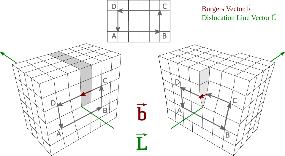
Labeled diagrams of edge and screw dislocations showing the dislocation line and Burgers vector directions. Plastic deformation proceeds by slip as dislocations move, permanently rearranging atoms. This clarifies why deformation becomes irreversible beyond the elastic limit. Source.
In amorphous materials such as polymers, the molecular chains uncoil or slide past each other during plastic deformation, explaining the flexibility of substances like rubber and plastics. In contrast, crystalline metals show plasticity through the motion of dislocations within their atomic lattice.
Elastic Limit and Yield Point
The elastic limit marks the maximum stress a material can withstand while still returning to its original shape when the force is removed. Beyond this point, the material enters the plastic region. The yield point is where plastic deformation begins in a noticeable, sustained manner.
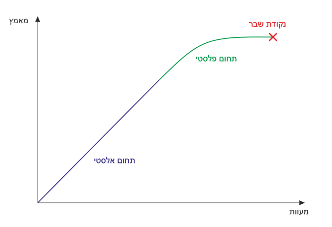
A schematic stress–strain curve with the elastic region shaded and the plastic region highlighted. The plot illustrates the transition at the elastic (yield) limit and the approach to fracture. Labels make the recoverable vs permanent deformation distinction explicit. Source.
Elastic region: Proportional relationship between stress and strain.
Plastic region: Stress increases slowly while strain continues to grow.
Yield point: Indicates onset of significant, irreversible deformation.
Elastic Limit: The maximum stress that a material can experience and still recover its original shape upon unloading.
Between the elastic and plastic regions lies the limit of proportionality, beyond which Hooke’s law no longer applies, even though some elasticity may remain.
Energy Considerations in Deformation
During elastic deformation, all the work done is stored as elastic potential energy within the material, which can be recovered when the force is released.
EQUATION
—-----------------------------------------------------------------
Elastic Potential Energy (E) = ½ kx²
E = Energy stored (J)
k = Force constant (N m⁻¹)
x = Extension (m)
—-----------------------------------------------------------------
In plastic deformation, not all energy is recoverable. Part of the energy is irreversibly converted into heat due to internal friction and atomic rearrangements, while the remainder contributes to permanent deformation.
Practical Implications of Elastic and Plastic Behaviour
The distinction between elastic and plastic deformation has significant practical implications in engineering, manufacturing, and materials science:
Design and Safety:
Engineers must ensure that components operate within their elastic limits under normal conditions to avoid permanent deformation or failure.Forming and Shaping Materials:
Controlled plastic deformation is used in processes such as forging, rolling, and extrusion, where metals are permanently shaped without breaking.Energy Absorption:
Materials that exhibit both elastic and plastic behaviour (like mild steel) can absorb significant energy before failure, making them ideal for crash protection and impact-resistant structures.Brittle vs Ductile Behaviour:
Brittle materials (e.g. glass, ceramics) show little or no plastic deformation before fracture, whereas ductile materials (e.g. copper, aluminium) display significant plastic deformation, providing warning before failure.Fatigue and Repeated Stress:
Repeated cycles of elastic and small-scale plastic deformation can cause fatigue failure over time, even below the ultimate tensile strength of the material.
Summary of Atomic Perspective
At the atomic level, the transition from elastic to plastic behaviour can be summarised as:
Elastic: Temporary bond stretching → atoms return to equilibrium → energy fully recoverable.
Plastic: Bond breaking and atomic rearrangement → permanent displacement → partial energy loss.
This atomic model links the microscopic interactions of atoms with the macroscopic mechanical properties observed in experiments, fulfilling the OCR specification’s requirement to “relate to atomic/molecular models and practical implications.”
Practice Questions
Question 1 (2 marks)
Explain the difference between elastic and plastic deformation of a material when a force is applied.
Mark Scheme:
1 mark: States that elastic deformation is temporary and the material returns to its original shape when the force is removed.
1 mark: States that plastic deformation is permanent and the material does not return to its original shape once the force is removed.
Question 2 (5 marks)
A metal wire is stretched by gradually increasing the applied force. The stress–strain graph for the material is shown below (diagram not included).
Describe and explain the behaviour of the wire from the start of loading up to fracture, referring to both the macroscopic and atomic processes involved.
Mark Scheme:
1 mark: Describes that in the initial linear region, the wire obeys Hooke’s law and stress is proportional to strain.
1 mark: Identifies that up to the elastic limit, the wire returns to its original shape when the load is removed.
1 mark: Explains that beyond the elastic limit or yield point, plastic deformation occurs and the wire does not regain its original shape.
1 mark: Mentions that plastic deformation involves movement of dislocations or slip between atomic planes, leading to permanent rearrangement of atoms.
1 mark: States that as stress increases further, the material necks and eventually fractures when the internal bonds can no longer withstand the applied stress.
FAQ
During plastic deformation, some of the work done on the material is converted into internal energy, increasing the temperature slightly.
This occurs because energy is dissipated as heat due to atomic rearrangements and friction between dislocations. Unlike in elastic deformation, where all energy is stored as elastic potential energy, only a portion is recoverable in the plastic region.
This heat generation can be significant in metals under repeated loading or forming processes.
Metals have a metallic bonding structure that allows layers of atoms to slide over one another easily via dislocation motion.
Ceramics, however, have ionic or covalent bonds, which are strong but directional. When stress is applied, these bonds resist rearrangement and fracture occurs instead of plastic flow.
As a result, metals are ductile, while ceramics are brittle, showing almost no plastic deformation before failure.
Dislocations make plastic deformation easier because they allow atomic planes to slip with less applied stress.
However, by hindering dislocation movement—for example, through alloying, work hardening, or adding impurities—the material’s strength increases.
This principle is the basis of strengthening mechanisms in materials engineering, where reducing dislocation mobility raises the yield stress and makes the material harder to deform permanently.
Polymers consist of long molecular chains that can both stretch elastically and slide plastically.
At small strains, the chains stretch and straighten, producing an elastic response.
At higher strains, the chains slide past one another, resulting in plastic flow.
The extent of each behaviour depends on factors like temperature, cross-linking, and strain rate. For example, cross-linked polymers (e.g. rubber) show more elasticity, while thermoplastics display greater plastic deformation.
Even minor plastic deformation can accumulate over time through cyclic loading, where the material is repeatedly stressed and relaxed.
This process creates micro-cracks and dislocation pile-ups, which gradually weaken the material. Eventually, these imperfections coalesce into larger cracks, leading to fatigue failure—a sudden break even when the applied stress is below the ultimate tensile strength.
Fatigue is a critical consideration in components subject to vibrations or cyclic forces, such as aircraft wings and bridge supports.

.svg)