
AP Syllabus focus: 'The electric field between two charged parallel plates with uniformly distributed charge is constant in magnitude and direction, except near the edges.'
A pair of parallel plates provides one of the clearest models of an electric field. This setup is important because it shows when a field can be treated as uniform and when that approximation stops working.
Parallel Plates as a Simple Field Model
When two large, flat plates are parallel and carry charge spread evenly over their facing surfaces, the region between them becomes a very useful electric-field model. The central idea is symmetry: the geometry looks essentially the same from many points between the plates, so the field behaves in a simple, predictable way. In AP Physics 2 Algebra, this matters because it allows the field between the plates to be described without tracking the effect of every tiny bit of charge.
This arrangement is used to model a uniform electric field.
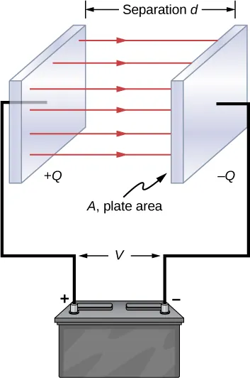
Electric field lines are drawn straight and parallel between oppositely charged plates, illustrating a region where the field’s direction is constant. The roughly even spacing of the lines represents a nearly constant field magnitude in the interior (a hallmark of the uniform-field approximation). Source
Uniform electric field: An electric field that has the same magnitude and the same direction at every point in a region of space.
In the middle region between the plates, the field is treated as approximately uniform. This means that a point near the center and another nearby point experience essentially the same field.
Why the Middle Region Is Uniform
Each plate contributes to the field in the space around it. Because the plates are parallel and the charge is uniformly distributed, the contributions combine in a very regular way between the plates. Side-to-side effects from different parts of a plate cancel, while the parts of the field pointing across the gap reinforce one another. The same pattern occurs at many locations in the central region, so the field there stays nearly unchanged from point to point.
This is an idealized model, but it is a very good one when the plates are large compared with the distance separating them. Under those conditions, most of the space between the plates is far enough from the boundaries that the edge region has little influence on the center.
Direction of the Electric Field
For oppositely charged parallel plates, the electric field between them points in a single overall direction: from the positive plate toward the negative plate. In the uniform central region, that direction does not rotate from place to place. If you imagine drawing field vectors there, they would be parallel to one another and straight across the gap.
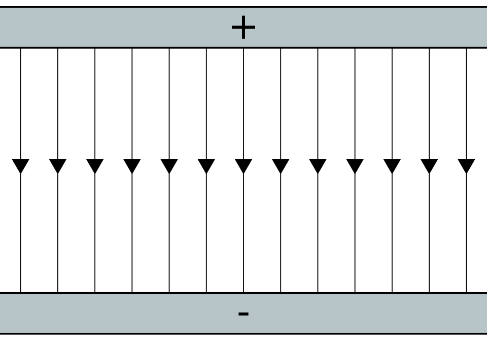
A schematic field-line map between two finite plates shows the interior region dominated by straight, parallel lines (uniform field) with mild outward curvature near the ends (edge effects). Because it is a clean line drawing, it works well for annotating direction (from + to −) and discussing where the uniform-field model applies. Source
Because the direction is constant in the middle, the field is easier to describe than the field around a single isolated charge. You do not see the field spreading outward in many directions. Instead, the pattern is organized and consistent across the interior region.
Magnitude of the Electric Field
The specification also emphasizes that the field is constant in magnitude between the plates, except near the edges. Here, magnitude means the strength of the field. In the central region, one location between the plates has essentially the same field strength as another nearby location, provided both are well away from the boundaries.
This constancy comes from the same symmetry that fixes the direction. Since the charge distribution and plate spacing remain the same across the middle region, the combined effect of the plates also remains the same. That is why the parallel-plate model is often used as the standard example of a constant electric field.
The nonuniform behavior near the boundaries is called edge effects.

This diagram contrasts the nearly uniform interior field (mostly straight lines) with the fringing field near the edges (lines curving outward). It visually explains why direction and magnitude cease to be constant near boundaries, even though the central region is well-approximated as uniform. Source
Edge effects: The behavior near the boundary of the plates where the electric field changes in magnitude and direction instead of staying constant.
What Happens Near the Edges
Near the edges, the simple picture breaks down. At the boundary of a plate, the charge distribution no longer surrounds the region in the same balanced way as it does near the center. There is no more plate beyond the edge, so the sideways cancellations that worked in the middle are incomplete. As a result, the field begins to curve outward and spread.
This means several changes occur near the edges:
the direction of the field is no longer the same everywhere
the magnitude of the field is no longer constant
the field pattern becomes less like the ideal uniform model
The field near the edges is still real, but it is more complicated. In many diagrams, this is shown by lines that bow outward rather than staying perfectly straight and evenly spaced.
Using the Model Correctly
When a problem says the plates are parallel and the charge is uniform, the usual assumption is that you should focus on the region well between the plates, not the narrow areas close to the rims. That is the part of space where the constant-field approximation is most reliable.
A good habit is to ask whether the point of interest is in the central region or in an edge region. If it is central, treat the field as having one direction and one magnitude throughout that area. If it is near an edge, be cautious: the field is no longer uniform, so a more detailed model would be needed.
The key physical idea is not that parallel plates create a perfectly constant field everywhere. Instead, they create an electric field that is approximately constant in magnitude and direction over most of the space between the plates, except near the edges.
Practice Questions
State how the electric field between two large charged parallel plates behaves in the middle region and how it behaves near the edges.
1 mark: States that in the middle region the field is constant or uniform in magnitude and direction.
1 mark: States that near the edges the field is not uniform, so the magnitude and/or direction changes.
Two large parallel plates have equal and opposite charge distributed uniformly over the plates. A student compares a point at the center of the space between the plates with a point near one edge.
(a) Describe the direction of the electric field at each point.
(b) Compare the magnitude of the electric field at each point.
(c) Explain whether the constant-field model is appropriate at both points.
1 mark: States that at the center the field has one consistent direction across the gap.
1 mark: States that near the edge the field direction changes or bends outward.
1 mark: States that at the center the field magnitude is approximately constant.
1 mark: States that near the edge the field magnitude is not constant and may vary from point to point.
1 mark: Explains that the constant-field model is appropriate in the central region but not near the edge because edge effects make the field nonuniform.
FAQ
Those drawings focus on the central region, where the field is approximately constant. They are meant to emphasize the main pattern, not every detail of a real setup.
If fringing were drawn every time, the most important idea for the middle region would be less clear at a glance.
There is no single cutoff that works for every situation. The approximation improves when the plate dimensions are much larger than the separation between the plates.
It also works best when the point being studied is far from the edges, so the fringing region is only a small part of the total space.
In the ideal AP model, plate thickness usually does not matter much. The main features are that the plates are parallel and the charge is distributed uniformly.
In real hardware, thickness can affect mechanical stability and edge shape, which can slightly influence how strong the edge effects are.
Several practical issues can disturb the ideal pattern:
plates that are not perfectly parallel
uneven spacing across the gap
bent or rough plate surfaces
nearby charged objects
nonuniform charging of the plates
These effects matter most when high precision is needed or when the plates are small.
The model is useful because many real plate systems have a large central region that behaves very much like the ideal case. That is often enough for accurate predictions.
Physics models do not need to be perfect everywhere. They need to capture the dominant behavior in the region that matters most.