
AP Syllabus focus: ‘A system can be modeled as a single object located at its center of mass.’
Modeling a multi-object system as one object is a powerful simplification for translational motion. Instead of tracking every part, you track the motion of one special point that represents the system’s overall location.
The center of mass single-object idea
When you replace a system with a single “equivalent” object, you are not claiming the system literally collapses to a point. You are choosing a model that correctly predicts the system’s translational motion while ignoring internal complexity that does not matter for the question.
Center of mass — the point that represents the average position of all the mass in a system, weighted by how much mass is located at each position.
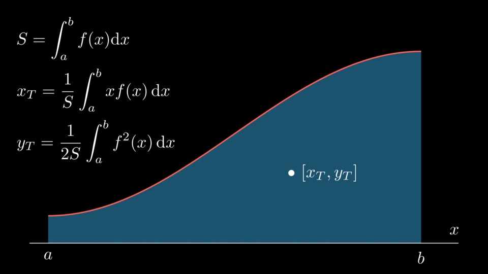
This diagram shows a region under a curve and the corresponding centroid/center-of-mass formulas, emphasizing that “center of mass” is fundamentally a weighted average of position. While AP Physics 1 typically uses discrete masses, the graphic highlights the same idea in the continuous limit. Source
In the single-object model:
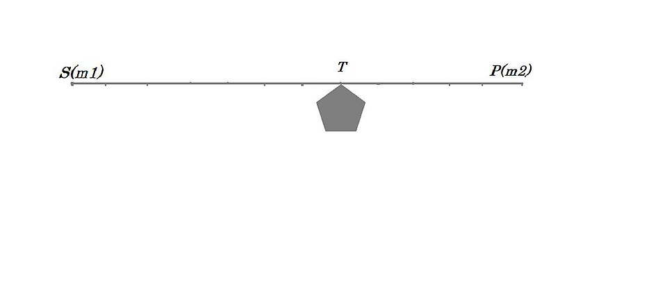
A two-body system balances at a point between the masses: the center of mass lies closer to the heavier mass because it is a mass-weighted average position. This picture supports the modeling move of replacing an extended/multi-object system by a single point located at the center of mass when analyzing translation. Source
The system is treated as if its total mass is concentrated at the center of mass.
The “object” you draw and analyse represents the entire system’s translation (how it moves from place to place), not its rotation or deformation.
What this model is (and is not) claiming
This model is appropriate when you care about questions like “Where is the system going?” or “How does its velocity change?” It does not automatically describe:
how parts move relative to each other,
stresses inside the system,
rotation about the center of mass,
shape changes.
Forces and motion in the single-object model
To use the center of mass as a single-object model, you focus on how the environment pushes or pulls on the system as a whole.
External force — a force on the system exerted by something outside the system (part of the environment), as opposed to forces between objects within the system.
A key idea for the model is that translational motion depends on the net external force on the system. That net external force produces the acceleration of the center of mass as if the entire system were one object.
= net external force on the system, in newtons
= total mass of the system, in kilograms
= acceleration of the center of mass, in meters per second squared
This equation is the mathematical statement of the syllabus focus: you may treat the system as a single object located at its center of mass, with mass equal to the system’s total mass.
What to include on the “single-object” free-body diagram
When you draw a free-body diagram for the system-as-one-object:
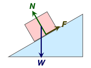
A free-body diagram isolates the chosen system and shows only external forces acting on it, drawn as vectors. In this inclined-plane example, the block’s weight, the normal reaction from the surface, and friction are shown as distinct external forces that can be vector-summed to find the net force. Source
Include only external forces acting on the system.
Do not include forces that system objects exert on each other, because they are not forces from the environment on the system.
Draw the forces as if applied at the center of mass of the system, consistent with the single-object replacement.
How to apply the model in problem-solving
Step-by-step modelling workflow
Choose the system (define clearly what objects are included).
Identify the environment (what can exert external forces).
Replace the system with a single dot at the center of mass.
Draw and label all external forces on that dot.
Choose axes suited to the motion being analysed.
Write component equations using the system form of Newton’s second law to relate net external force to center-of-mass acceleration.
Interpreting the result correctly
After finding the center-of-mass acceleration or motion:
Treat the result as the motion of the system’s “overall location.”
Remember that individual parts of the system may accelerate differently than the center of mass, especially if the system is stretching, compressing, or rotating.
Use the model only for claims about translation unless additional information is provided.
When the single-object model is most useful (and its limits)
The center-of-mass model is most useful when:
the system’s internal arrangement is complicated but irrelevant,
the question asks for overall acceleration, overall motion, or trajectory of the system,
you can reliably identify the net external force.
The model is limited when:
rotational effects are central to the question,
internal motion determines the outcome you are asked about,
external forces act in a way that depends strongly on where they are applied and torque matters (then translation alone is not enough).
Practice Questions
(2 marks) A system consists of two carts stuck together and moving on a horizontal track. Explain how you would model the system as a single object to find its acceleration when pushed by an external horizontal force .
States that the system can be treated as one object at the centre of mass with total mass (1)
Uses (or for horizontal) and notes only external forces are included (1)
(5 marks) Two blocks are connected and pulled along a flat surface by a horizontal force applied to one block. You are asked for the acceleration of the two-block system. Describe, using the centre-of-mass single-object model, (i) what you include on the system free-body diagram, (ii) what mass you use, and (iii) what equation relates the forces to the acceleration.
Identifies the system as “both blocks together” and places the single object at the centre of mass (1)
Includes only external forces on the system FBD (e.g., applied force, friction from floor if present, weight and normal if relevant) (2)
States the mass used is total mass (1)
Writes and links to the system acceleration (1)
FAQ
No. For extended or separated objects, the centre of mass can lie in empty space (for example, between two separated masses). The single-object model still uses that point for translational motion.
Not necessarily. Drawing them at the centre of mass is part of the translational model. It keeps the focus on net external force and translation, not where each force is applied.
You must be careful: $M$ may not be constant, and the “system” boundary matters. The centre-of-mass approach can still work, but only with a clearly defined system and accounting for mass transfer.
Yes for translation: the centre of mass can accelerate while the system rotates. However, the model alone will not predict angular acceleration or rotational energy without additional rotational analysis.
Only if the objects move together without relative motion. If parts accelerate differently (slipping, stretching, separation), $\vec{a}_{\text{cm}}$ describes the system’s overall acceleration, not each component’s.
