
AP Syllabus focus: 'Equipotential lines are lines of equal electric potential. Isolines are perpendicular to electric field vectors, and electric field vectors point toward decreasing potential.'
Equipotential maps turn electric potential into a visual pattern. To use them correctly, you must know what equal-potential lines mean, how field vectors meet them, and how to identify the direction of lower potential.
Equipotential lines and isolines
An equipotential line marks every point on a diagram that has the same electric potential. It is a way to picture potential in space without listing a separate value at every location.
Equipotential line: A line connecting all points that have the same electric potential.
If two points lie on the same equipotential line, their potential values are equal, even if the line curves. The line is therefore a map of constant potential, not a path that a charge must follow.
The more general term isoline is used for any line connecting equal values of some quantity.
Isoline: A line drawn through points that share the same value of a quantity.
In this topic, equipotential lines are isolines because they connect equal electric potential. Thinking of them as map contours is helpful: each labeled line shows one exact potential value, and moving to a different line means moving to a different potential.
Why electric field vectors are perpendicular
The key geometric rule is that electric field vectors are perpendicular to equipotential lines.
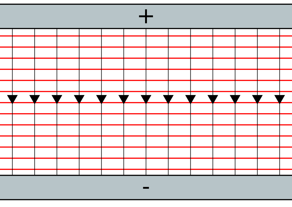
Uniform-field diagram for a parallel-plate setup: electric field lines are straight and parallel, while equipotential lines are straight and perpendicular to the field. The right-angle crossings visually encode the rule is normal to constant- lines, so moving along an equipotential does not change potential. Source
Perpendicular means they meet at right angles. This is true at every point, even when the equipotential line is curved or irregularly shaped.
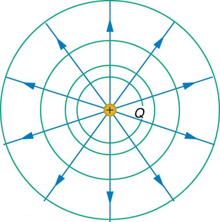
Point-charge diagram: equipotential lines form concentric circles, while electric field lines radiate outward (for a positive source). At any point, the local tangent to an equipotential circle is perpendicular to the radial field direction, illustrating why the perpendicularity rule holds even for curved maps. Source
You should imagine the relationship locally. At one point on a curve, draw a tiny straight segment tangent to the line. The electric field vector at that point crosses that local segment at a right angle.
No change along the line
An equipotential line has no change in potential along its length. Because of that, the electric field cannot point partly along the line. If it did, the field would have a tangential component, and the potential would change as you moved along the line. That would contradict the idea of an equipotential.
Instead, the field points across equipotential lines, from one potential value to another. This is why field vectors are drawn normal to the isolines rather than tangent to them.
Direction toward decreasing potential
Electric field vectors point toward decreasing potential. When you read labels on an equipotential map, the field points from higher-numbered lines to lower-numbered lines. For instance, if nearby lines are labeled 18 V, 12 V, and 6 V, the field points from 18 V toward 12 V and then toward 6 V.
This direction rule is essential because a perpendicular line by itself has two possible directions. The labels remove that ambiguity. Once you know which side has the lower potential, you know which way the field vector points.
Reading maps from potential labels
An equipotential map can be read systematically. Start by locating the potential value at the point of interest. Then identify the neighboring region with larger potential and the neighboring region with smaller potential. The electric field vector must cross the nearby equipotential line at a right angle and point toward the lower value.
This method works for straight, curved, widely spaced, or tightly packed lines.
The shape of the lines changes from one physical situation to another, but the interpretation rule does not change.
Curved maps and local direction
On curved equipotential lines, the field direction can change from point to point. You should not try to assign one single direction to an entire curved line. Instead, determine the direction at the exact point you are considering. Draw a short arrow perpendicular to the line there, and orient it toward the lower labeled potential.
This local view prevents a common error: treating a curved equipotential as though it had one global direction. The field responds to the geometry at each point, not to the overall shape alone.
Useful interpretation checks
You can test your reading of a diagram with a few quick checks:
Points on the same equipotential line must share the same potential value.
A field vector should never lie along an equipotential line.
At each point, the field should cross the line at a right angle.
The arrow should point from higher potential toward lower potential, not the other way around.
These checks are especially helpful when a diagram is crowded or when the equipotential values are not arranged in a simple left-to-right pattern.
Common misconceptions
One frequent mistake is assuming that the field points toward the largest numerical value because the number seems more prominent on the page. In fact, the field points downhill in potential, toward smaller values.
Another mistake is drawing arrows between two lines without making them perpendicular. Even if the direction from high to low is correct, the geometry is still wrong unless the arrow crosses the isolines at right angles.
A final mistake is confusing an equipotential line with a physical boundary. It is not a wall or a wire by itself. It is only a graphical representation of where the potential happens to be the same. Careful attention to labels and right-angle crossings lets you recover the field direction directly from the isolines.
Practice Questions
Three straight vertical equipotential lines are labeled 15 V, 10 V, and 5 V from left to right.
State the direction of the electric field between the lines, and state how the field is oriented relative to the equipotential lines.
1 mark: States that the electric field points from 15 V toward 5 V, so from left to right.
1 mark: States that the electric field is perpendicular to the equipotential lines.
A map shows four concentric equipotential lines centered at point O. From the center outward, the lines are labeled 40 V, 30 V, 20 V, and 10 V. Point P lies on the 30 V line on the right side of the map.
(a) State the electric potential at point P. (1)
(b) Describe the direction of the electric field at P relative to the 30 V line. (2)
(c) State whether the electric field at P points toward O or away from O, and justify your answer using the equipotential labels. (2)
(a) 1 mark: States that the potential at P is 30 V.
(b) 1 mark: States that the field is perpendicular to the 30 V equipotential line.
(b) 1 mark: Indicates that this perpendicular direction is taken at point P specifically.
(c) 1 mark: States that the field points away from O.
(c) 1 mark: Justifies that the potential decreases outward from 40 V to 10 V, so the field points from higher potential to lower potential.
FAQ
Yes. A single potential value can occur in more than one place, so an equipotential map may show separate pieces with the same label.
They are still part of the same potential level, even if they are not connected on the drawing.
The rule does not change. The electric field still points toward decreasing potential.
For example, if the labels go from 0 V to -5 V to -10 V, the field points toward -10 V because that is the lower potential.
A line diagram is usually a two-dimensional slice of a situation that may really be three-dimensional.
In three dimensions, equal-potential locations form surfaces. On a flat page, those surfaces are often represented by lines in a cross-section.
The shape of equipotential lines depends on the geometry of the source arrangement and the surrounding boundaries.
If the setup is highly symmetric, the equipotential pattern is usually symmetric too. If the setup is uneven, the pattern becomes stretched or distorted.
It means the potential is changing rapidly with position in that region.
That usually indicates a stronger electric field there, because the field reflects how quickly potential decreases with distance.